Two accomplishments today. First, I was able to use the Atmel 328P chip outside of the Arduino board. What is the benefit of this? First, cost.. The Arduino UNO is currently $25 but the Atmel 328P is only $1,86 if you buy it on eBay, and only a few dollars more if you buy it from some place else. However, you are going to need a few more components such as a 16MHz crystal, a few capacitors, resistors, voltage regulator, wires, and something mount it on.. All told, probably another $5. Now you won’t have the nice board, the USB to serial converter, the 3.3volts power connection (could easily use two resistors to create a voltage divider to step the 5V down). So it is not an apple to apple comparison. But if you want to have these chips in a lot of little projects, then you are going to have a lot more options when the price gets to the $5-$10 range instead of the $25 range.
Also, you can compact the design down to just what you need. You have more control over the final form factor. And this is also a good step into the world of microcontrollers in general. Before you know it, you will be programming the entire Atmel family of chips..
So, how to get started. There were a number of really good tutorials that I looked through.:
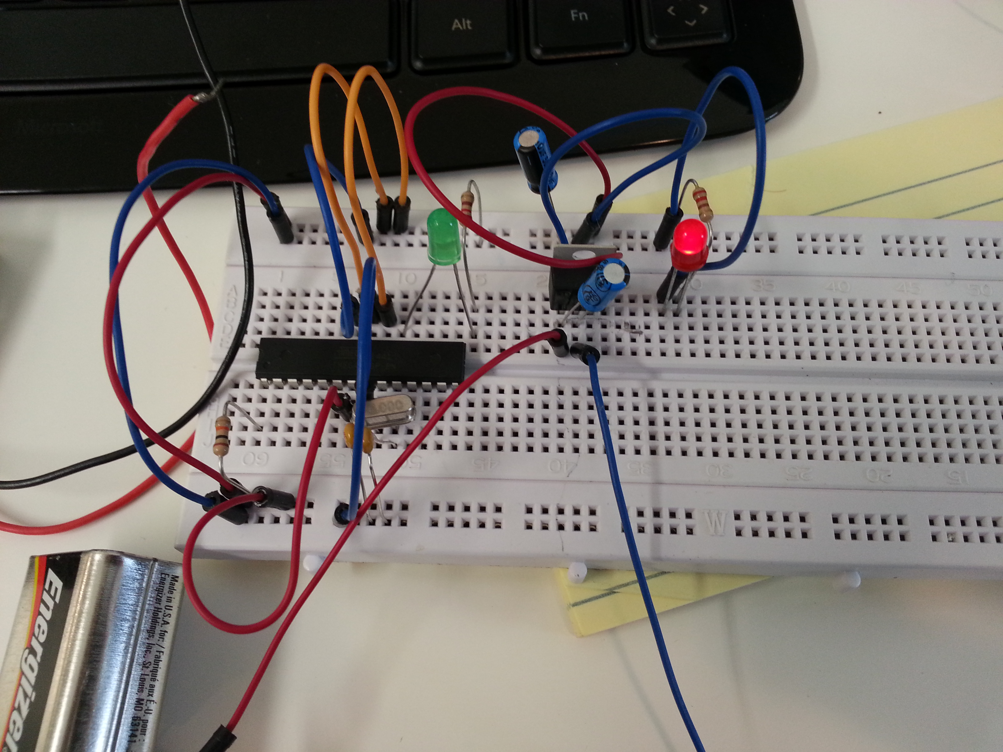
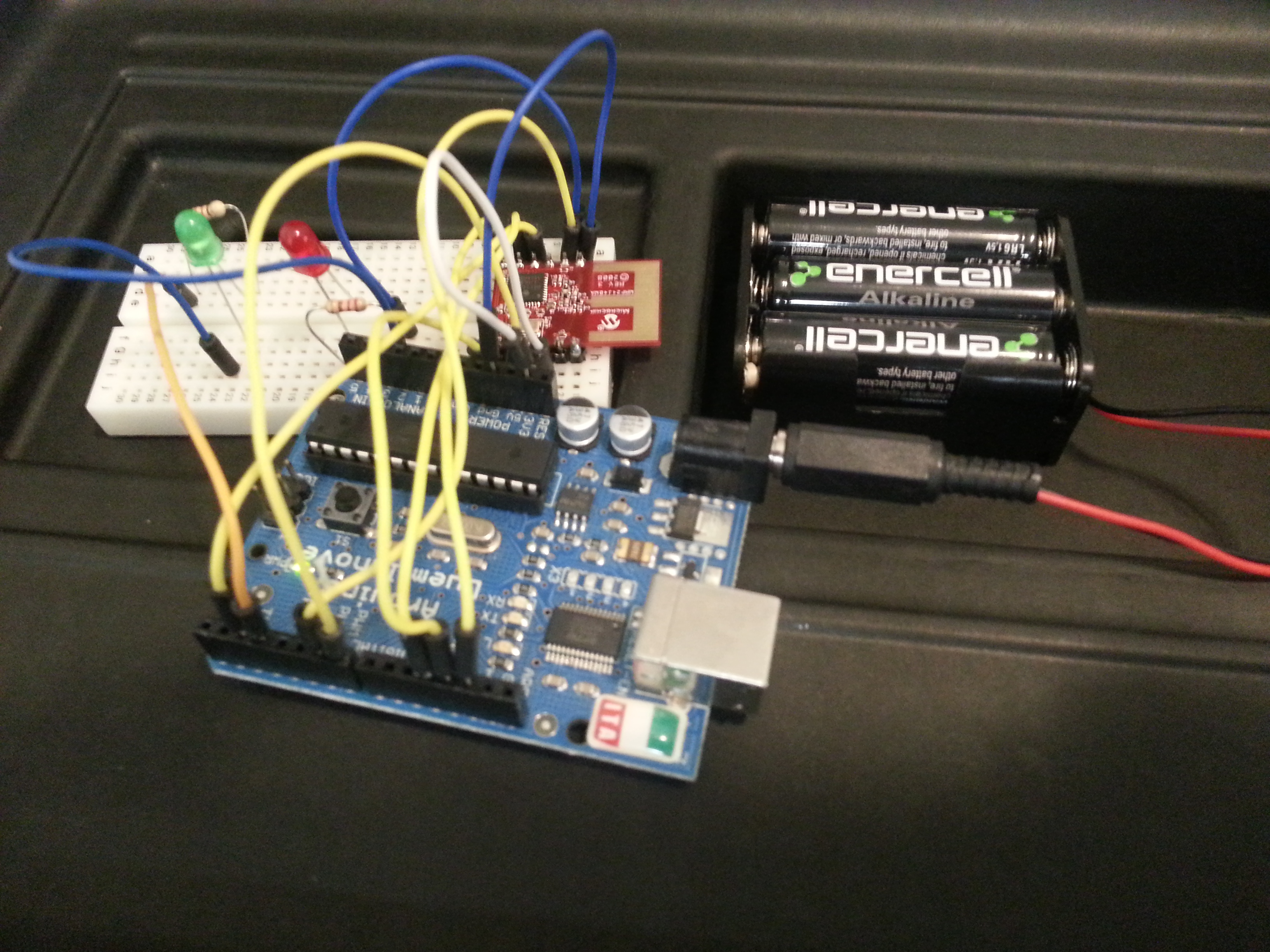
Here is the configuration I used to burn the boot loader onto the Atmel 328P.
To program it I just inserted it into the Arduino, downloaded the program, and then removed the Atmel 328P.
Here is the configuration I have it to run the “Blink” Example (This is the “hello world” of arduino)
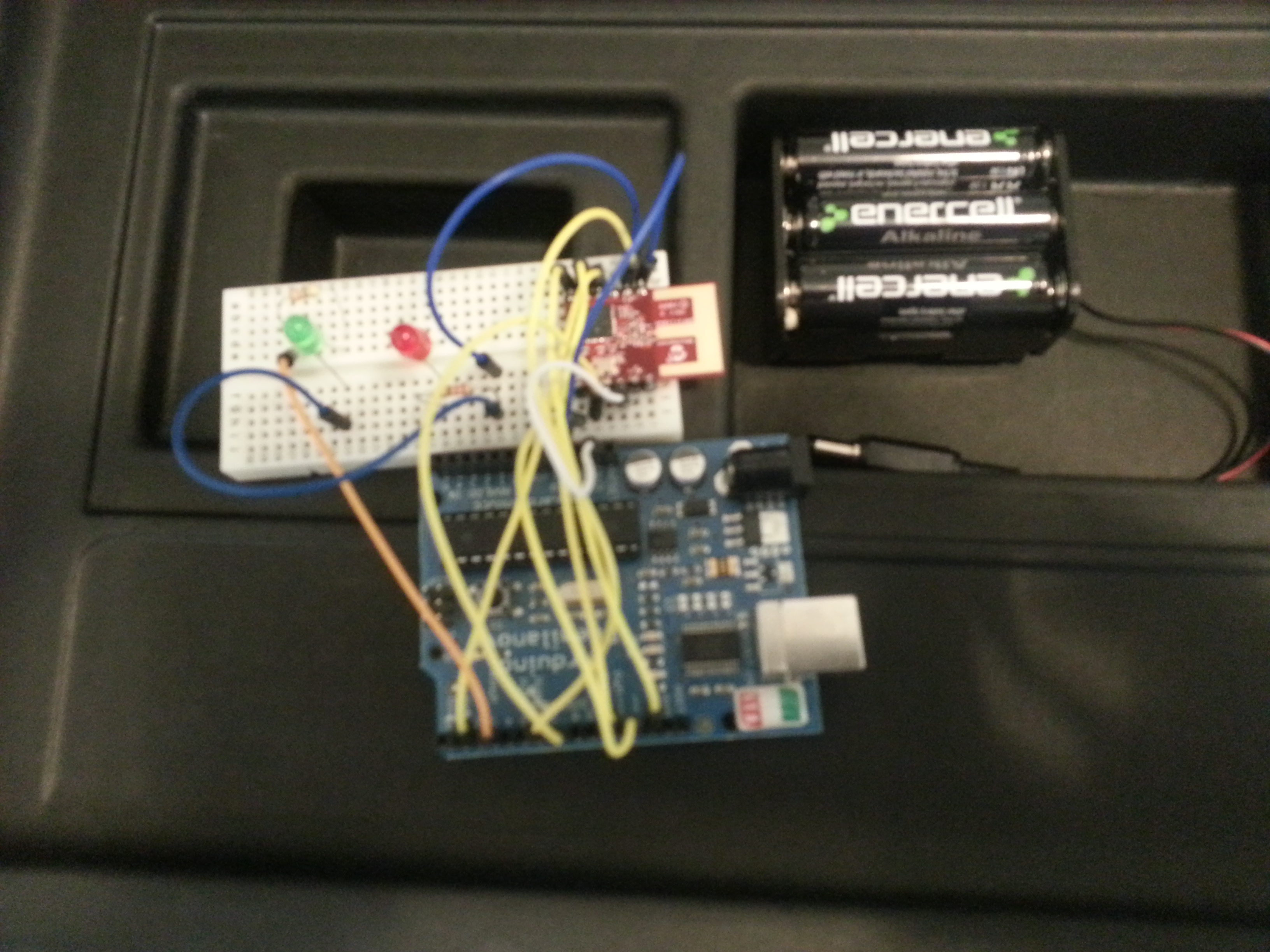
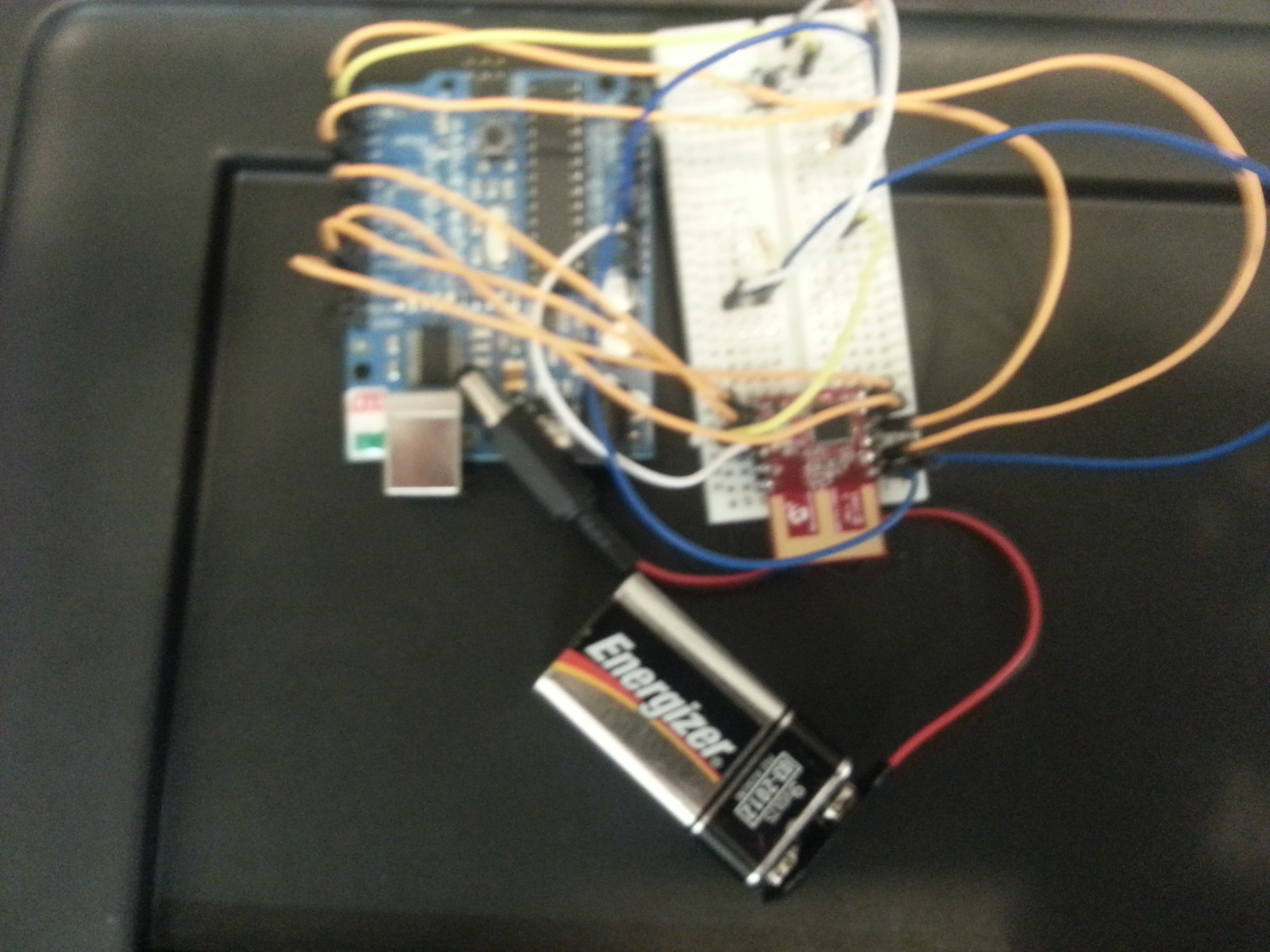
My other accomplishment today was getting the MicroChip MRF24J40MA module working with two Arduinos. Starting out small, I have it so you can press a button on one arduino and a LED comes on the other: (It really needs to be shown in a video. I hope to upload one in the next few days)
Here is some more info about the module and how to use it:
Now I would like to be able to combine the two above so that I only need the Atmel 328P and the MRF24J40MA module. Then I will hook up some sensors (light, temperature, humidity, gas, accelaramotrs, etc.) Then I plan to have some of these modules through out the house feeding data into a central unit that then is loading it into a database. Then I will be able to see how different parameters of my house changes over time. I think I should be able to have a working prototype up by the end of day tomorrow.
My youngest son has thousands of Magic cards that he wants to scan. Instead of doing it manually, I thought it would be good to create a simple device to take a picture, move the card from the top, take a picture, etc.
Here you can see one of the early iterations of it actually working. It uses a PC cooling fan to pick up the top card. There is a light sensor on the bottom of the fan that is used to determine if the fan is in contact (and remains in contact) with the fan. There is one servo that moves it up and down, and another that moves it left and right. An arduino is used to control the fan and servos and monitor the light sensor. This is hooked up to a laptop that has a simple Python program running on it that uses the libraries from OpenCV to take the picture. The Python program communicates with the Arduino via the serial port.
Here is a video of it in action:
This was created a few weeks ago. It took about 20 hours of experimentation, but it has scanned hundreds of cards. There is quite a bit more work to be done on it to make it work as well as we would like.
Teaching kids the basics of electronics and programming is something that I have been working on doing through my GadgetCamps. Â The GadgetCamps is 100% hands on. Â Hooking up circuits, typing in code, seeing how things work. Â There are many ways to make things “hands on”. Â The TeleScrap Book takes a unique approach. Â And it is Arduino based!
I had three weeks of Arduino camps for middle school kids. It was a big hit.
Today, I see this video that has an awesome introduction to the Arduino LOL (Lots of LEDs) shield. It is a wonderful little video that will bring a smile and inspiration to anyone who watches it.
Last week we had 6 middle school students at our first GadgetCamp. That was just the perfect number of students for the space at the Mathnasium that we are using.
The kids learned many things. How to identify the parts in their kits such as the Arduino microcontroller board, the usb cable, LEDs, resistors, wires, prototyping breadboards, peizo speaker, and buttons. They also learned to identify the parts of the Arduino board such as the usb connection, power connection, the digital pins, the analog pins, gnd pins, 5V pin, reset button, etc.
Then we go through the process of hooking up the Arduino to the computer and downloading the sample “blink†sketch. (Sketch is what an Arduino program is called in the Arduino world.) This is usually where we run into some time consuming problems due to different versions of windows, issues with the FTDI driver (FTDI makes the chip that is used to create the USB to serial connection used on the Arduino board), and issues with identifying the COM port that the Arduino is actually using.
Once passed, that we go through the blink sketch that turns on and off the 13th pin/connection on the board. This pin has its own LED built on the board. The blink program introduces a lot of new concepts and symbols that we go over. We learn about comments (/* */ and //). Learn about the two functions that must be defined in an Arduino program (setup() and loop()). We mention that the void in the function declaration is required, but that understanding about return types of functions is something that will not be covered in this camp. The purpose of the () is mentioned, but it is not expected that this is fully grasped at this stage. We also talk about the need and purpose of {}. And we point out how every statement has to end in a ;.
In the Blink sketch we go over the pinMode, digitalWrite, and delay functions that are used. Then we begin altering the blink program. What happens if you comment out the first delay? The light never comes on. Why? What happens if you comment out the second delay? The light never goes off. Why?
Challenge: Can you make the light stay on for twice as long as it is off? (Solution: Change delay interval after the digitalWrite(13, HIGH); to be twice as much as the digitalWrite(13, LOW);)
Challenge: Can you make the light blink one time long and then one time short? (Solution: Copy and past the 4 lines of the blink program and alter the delay times.)
From here we can move into Morse code and start sending out SOS and their initials.
Next we switch gears and learn about the prototyping breadboard. The most difficult part is understanding how the breadboard is connected. I have some better explanations and demonstrations planned for next week. And I think one thing that will help is to have better visuals to use in class. A cut away of the board would be useful. To the students, the prototyping breadboard looks like a grid of holes. The idea that some are connected together in a certain way is something that will take experience working with the prototyping breadboard to fully grasp.
Next we hookup a wire from the GND pin on the Arduino to the connection running on the side of the prototyping breadboard and a connection from the 5V to the connection running on the other side. Then we try hooking up our first LED and resistor. Here it is very, very important that the cathode of the LED (the shorter pin) to the ground side, then use a resistor (200 ohms) to connect to the anode of the LED. Then the resistor goes across the middle and hooks up to the other side of the prototyping breadboard. Then we take a wire to connect the resistor to the 5V connection on the side. Then the LED glows. During this process I explain that the LED will only work one way. The shorter pin has to be hooked up to ground. The longer one has to be hooked up to V+. I have them switch around the LED to demonstrate that it will not work the other way around.
The reason it is important to hook it up in this fashion is that it only takes removing the wire from the 5V+ connection and reconnecting it to an Arduino digital pin to have the Arduino control the light. At this point we usually go and connect multiple LEDs. This week I gave everyone red, yellow, and green LEDs to allow them to create a traffic light. All three are hooked up on the breadboard, and then we connect them to the Arduino. Pins 13, 12, 11. Then they have to modify the blink program by adding two pinMode lines and then the necessary delay and digitalWrite lines to make the lights blink like a traffic light. In the class this week we had an additional challenge of having two sets of traffic lights and to make them come on just like a real traffic intersection. They did a really good job.
Also, at this point we have them hook up as many lights as they want and create a pattern of blinking lights.
Now we switch gears again and begin working on constructing our electronic dice. For the case we have a cardboard box. They draw two squares on it and 7 circles in each square for the places that the LEDs need to go. Then using a tack they put two holes in each circle for the leads of the LEDs to go through. Then they put the LEDs in the cubes. I have a selection of LEDs that they can choose from. Green was the most popular color this week.
They put in the 14 LEDs for their dice, then bend the longer lead of the LED (the anode), to hold the LED in place and to make it easier to identify the cathode (shorter lead) which all need to be connected together. I have precut black wires for them to use and to connect using a wire wrapping tool. They connect all the cathodes together.
Then I have them connect a long wire that is either red, yellow, or white (I’ve gone through many spools of wire…). They connect this to the anode. I also have them remove the cover for the adhesive on the small prototyping breadboard to have it attach to the bottom of the box. Then they connect all the wires to this. This will then have the resistors and then the connection to the Arduino. The idea is to make it easier to connect and disconnect the Arduino from the electronic dice so that they can use it another project.
The wire wrapping is the end of the first day. The first camp we were mostly done with wire wrapping the first day. This week it took a lot of time. We ended up doing a lot of wire wrapping the second day too.
On the second day, we checked to make sure all the lights came on. We learned about creating our own functions. Started with just creating the “dot†and “dash†function for their Morse code program. We also covered variables, == comparison, the “if†statement and the “random†function. In the first week we also covered the piezo speaker and the tone function. This week, we barely mentioned it yesterday. Also, in the first camp we had the button hooked up on day two. We have not gotten to this yet.
This week, we have a lot of ground to cover on the final day of camp. I write some more about it later.
It is great to see how smart these kids are. I want to find some way to keep them motivated and making progress. For these reason, I am setting up monthly meetings for a “Electronics and Robotics Club†at the Barbara Bush Library. I’ve created Facebook events for the meetings. You can go there to find out more:
We are only 1 week away from our first Electronics Camp for Kids that will teach basic circuits and programming to kids in middle school. We had our first run through today. Everything went well.
Supplies for the electronics camp are coming in. I am now the the proud owner of 15 Arduino boards. We have hundreds of LEDs, buttons, resistors, wires and more than a dozen breadboards.
We have a number of people signed up, but it would be good to have a few more. Check out www.GadgetCamps.com to learn more and sign up.
Earlier, I had published a post about my implementation of the MySimon game. Recently I got some arcade buttons and was able to make the game a lot more enjoyable to play. Here is the way it looks now:
Today, I gave my first Arduino lesson to my sons (ages 8 and 12) and their friend (age 13). It only covered identifying parts of the arduino board, hooking the arduino to the computer, starting the IDE, using the built in blink example, changing the example to flash S.O.S. in Morse Code, refactoring the example so that it uses a “dot†and a “dash†function, and then writing something else in Morse Code of their choice.
The lesson print out is below, but let me give some insight into how it went.
My younger son (8 years) had some trouble with putting the “delay†command between the digitalWrite(13, HIGH) and digitalWrite(13, LOW). Delaying while the light is off made sense to him, but using it to keep the light on was counter intuitive and difficult for him to grasp. I need to find a good way to explain it.
My older son (12 years) had no trouble with creating the basic function. The only mistake that he had trouble with was putting the code in between () for the dot and dash functions he defined. I explained this and he was on his way. He even created a function for each letter so that he could just spell out the words using function calls like this for “hiâ€:
h();
i();
My son’s friend (13 years) had no trouble. He was able to do the morse code with no trouble.
I think all in all, this lesson would work out best for 6 grade and above..
—-Lesson 1—–
Arduino Lesson 1 – Blinking LED 13
Learning Objectives:
· How to hookup the Arduino to the computer
· How to open the Arduino IDE
· How to type a simple program into the Arduino IDE that blinks the built in light on the board
· Learn the basic syntax and structure of an Arduino program (Arduino programs are called sketchs)
· Learn the commands pinMode, digitWrite, delay
· Learn how to define a function
What you will need:
· Computer
· USB cable
· Arduino Duemilanove Board
· Arduino software (assumed to already be installed on the computer)
Activity 1: Take a look at the Arduino board
Try to identify the following items:
· Digital pins 0-13
· GND pins (how many of them are there?)
· 5V
· 3V
· Analog In 0-5
· Pins marked PWM
· Pins marked “TX†and “RXâ€
· Pin marked Reset
· Pin marked Aref
· USB connection
· Power connection
· ICSP pins
· Reset-EN label
· Reset button
· Lights marked “Lâ€, TX, RX, PWR
What do the following terms mean:
Digital
Analog
GND
5V
3V
PWM
TX
RX
Reset
(aref we will learn about later)
Activity 2: Connect the Arduino to the computer using the USB cable. Which lights come on? What do you think that means?
Activity 3: Open up the Arduino IDE. Go to the “file†menu, choose “examplesâ€, then “basicâ€, then “blinkâ€
Take a moment to look at this program. This is written in a computer language called “Câ€. There are several things that you should know about “Câ€
1. It is case sensitive. So “hello†is different than “Helloâ€. (notice the first one has a lower case ‘h’ and the second one has a upper case ‘H’)
2. Every statement must end with a semicolon “;â€. What is a statement? A statement is a command that you give to the computer. Look at every line that ends with “;†to see examples of statements
3. function are commands that are built in and that you can define yourself. There are two functions that are defined here: setup and loop. These are very special to the arduino. When defining a function you have to specify if the function will “return†a value. Since these do not return a value, you see that “void†is listed before their names. Do not worry about understanding this now. It will make more sense later.
4. After the function name is defined there is a set of () with nothing in them. This is where the parameters of the function will go. “setup†and “loop†do not take parameters so they are blank. Again, do not worry about understanding it now. It will make more sense later.
5. The actual code of the function is contained within in braces: {}
The “setup†function gets called one time.
The “loop†function gets called over and over and over again.
Take a look at this program. Can you figure out what it does?
In the setup function there is a statement: pinMode(13, OUTPUT); This set the Digital Pin 13 to be in Output mode. This means we will be sending a value to this pin. You could specify INPUT which would mean that you would want to “read†a value from this pin. This we will do when we get to buttons.
In the loop, there are two functions used: digitalWrite and delay. digitalWrite will turn “on†the pin when it is “HIGH†and turn “off†the pin when it is “LOWâ€. delay will wait the specified number of milliseconds before the program continues.
How many milliseconds are in a second?
How about in 10 seconds?
How about in a minutes?
Activity 4: Upload the sketch to the arduino and see what happens. Do this by click “file†and then “upload to I/O boardâ€.
Notice which lights blink as it is uploaded. Then what happens. Does it do what you thought it would?
Click the “reset†button. Now what happens?
Activity 5: Blink S.O.S in Morse Code.
SOS is dot dot dot dash dash dash dot dot dot wait and then repeat it again.
Dots mean that the light is on for a short time, and dots mean the light is on for a long time. How can you modify this program to make the lights blink this way?
Activity 6: Use a function to make our code nicer.
See how we use the digitalWrite(13,High), delay(…), digitaWrite(13, LOW), delay(…) over and over again for the dash and the dot. And in our code it is difficult to make out where the dots are and where the dashes are.
Let’s make our code easier to read by defining two functions, and then using them.
Define one function called dot like this:
void dot() {
…. Put the code here to make a ‘dot’
}
And one for dash like this:
void dash(){
… put the code for a dash here
}
Now our loop function should read
void loop() {
dot();
dot();
dot();
dash();
dash();
dash();
dot();
dot();
dot();
}
Notices how the dots all blend together? How can we fix that?
The Arduino microprocessor is a very affordable embedded systems solution. It costs about $20 per unit, and can be program easily in C. It has easy access to digital input and output pins, as well as analog input pins. In combination with the WiShield it allows for you to control lights, motors, and more over the network as well as monitor temperature, humidity, noise, etc.
This video provides a basic demonstration of controlling three LED lights over the wifi network at my home via a web browser on the iPhone. This provides the very basics of what you need to get started with the WiShield and controlling things over the wireless network.
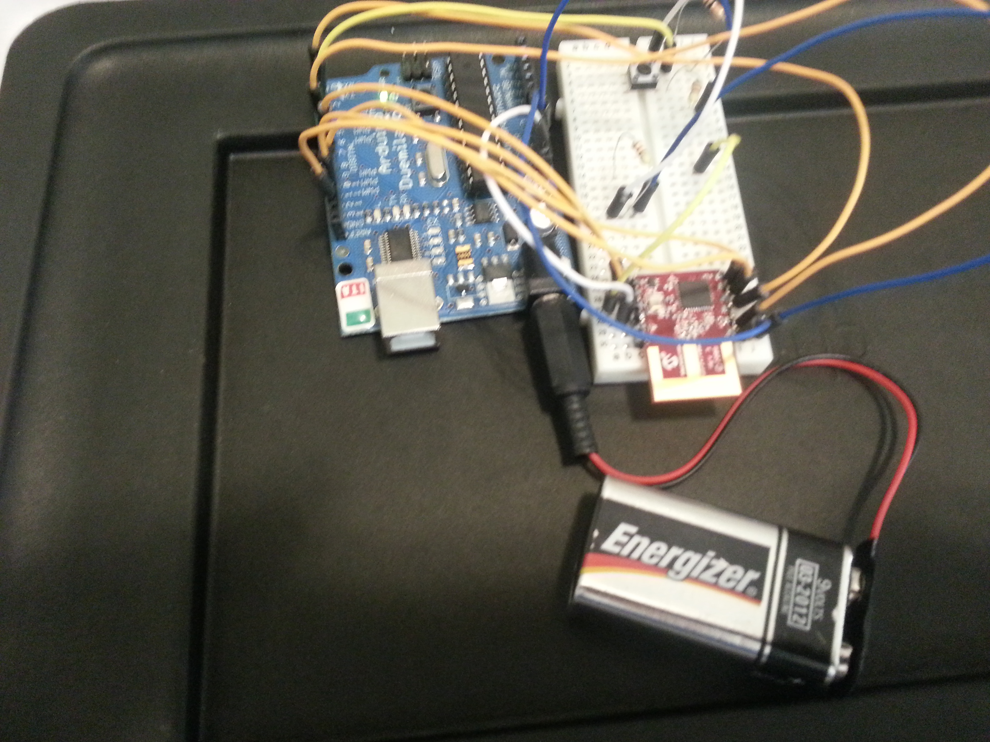
Here is a picture of the Arduino completely disconnected from the computer. It is being powered by a 9Volt battery and is completely portable.
Here is a video demonstrating the Arduino + WiShield in action:
By going to the following webpage on any computer in my home network, I am able to control the state of the lights:
Before giving you the code and circuit layout, let me tell you a little about the journey to this point.
I saw the WiShield on eBay I saw the LinkSprite CuHead WiFi Shield for Arduino for sale for $55 + $5 shipping. I thought it would be worth experimenting with. (As of 7/3/2011 it can still be bought on ebay cgi.ebay.com/ws/eBayISAPI.dll?ViewItem&item=110708459270#ht_2643wt_923) Here is some critical information from the ebay listing:
This is the shield you need to get Wi-Fi connectivity to your Arduino-based project! This shield provides 802.11b connectivity and is a direct drop-on plug-and-play solution to your Arduino Diecimila/Duemilanove/Uno.
Compatible with Asynclab wifi shield!
Shield Features
Add-on shield built for Arduino Diecimila, Duemilanove and Uno
Dimensions, shape, even color match exactly!
True plug-n-play solution
Uses SPI for host communication (max speed 25MHz)
All Arduino headers brought out for easy access
Easy access reset button on-board
On-board PCB antenna
Switchable interrupt pin usage between INT0 and digital pin 8
Switchable LED on digital pin 9
Switchable CS pin for serial flash between digital pin 10 and digital pin 7[1]
Wi-Fi Module Features
802.11b Wi-Fi certified
1Mbps and 2Mbps throughput speeds
Supports both infrastructure (BSS) and ad hoc (IBSS) wireless networks
Interrupt (Uses only one of the following, depending on jumper setting)
INT0 : Arduino pin 2 (port D, pin 2)
DIG8 : Arduino pin 8 (port B, pin 0)
LED : Arduino pin 9 (port B, pin 1)
To regain use of this pin, remove the LED jumper cap
5V power
GND
If you setup the serial dataflash CS pin to use pin 10, then the WiFi module will not be usable. In order to use the dataflash and WiFi concurrently, the dataflash jumper CS pin must be set to pin 7.
Several key things that I should have realized from this listing that would have saved me a lot of time.
First thing I should have read was “Compatible with Asynclab wifi shield!†This would have led me to the AsyncLabs Wiki and would have saved me a lot of time. And it would have led me to download the needed library and example files from the GitHub repository. Installing these files just required putting them in the “libraries†folder under the “arduino†folder on my PC.
Once I did this, I saw the example sketches (arduino programs) in the IDE:
The WiShield library includes support for both server and client applications. The individual apps are included as sample sketches but to switch between the two will require rebuilding the WiShield library as it requires reconfiguration of some variables. The library is configured as a webserver by default. To switch between modes:
Uncomment the appropriate mode, APP_WEBSERVER or APP_WEBCLIENT in the apps-conf.h file in the WiShield directory.
Depending on the mode you want the WiFi module to run, you have to comment out and uncomment out lines in the apps-conf.h file in the WiShield library folder. It continues with this note:
Delete all the object files (files with an extension of ‘.o’) in the WiShield directory.
Delete the ‘applet’ directory in the WiShield/examples/WebServer/ or WiShield/examples/WebClient/ directories.
Restart the Arduino IDE to rebuild the library in the appropriate mode.
I could not find any “.o†files or “applet†directory to delete. I did restart the Arudino IDE, but I am not 100% sure this was required.
At the top of all the examples, there is this section of code that you need to configure for your network:
// Wireless configuration parameters —————————————- unsigned char local_ip[] = {192,168,1,22}; // IP address of WiShield unsigned char gateway_ip[] = {192,168,1,1}; // router or gateway IP address unsigned char subnet_mask[] = {255,255,255,0}; // subnet mask for the local network const prog_char ssid[] PROGMEM = {“ssid"}; // max 32 bytes
Set the IP address and the default gateway according to your network. The SSID needs to be replaced with the name of your wifi network.
The “security_type†needs to be set according to your network. It supports “openâ€, “WEPâ€, “WPAâ€, and “WPA2â€. On my network, I run WPA2, so I set this to “3†as indicated in the comment by this value in the code above.
WPA2 only requires a passphrase, which I put where it says {“passphraseâ€} above.
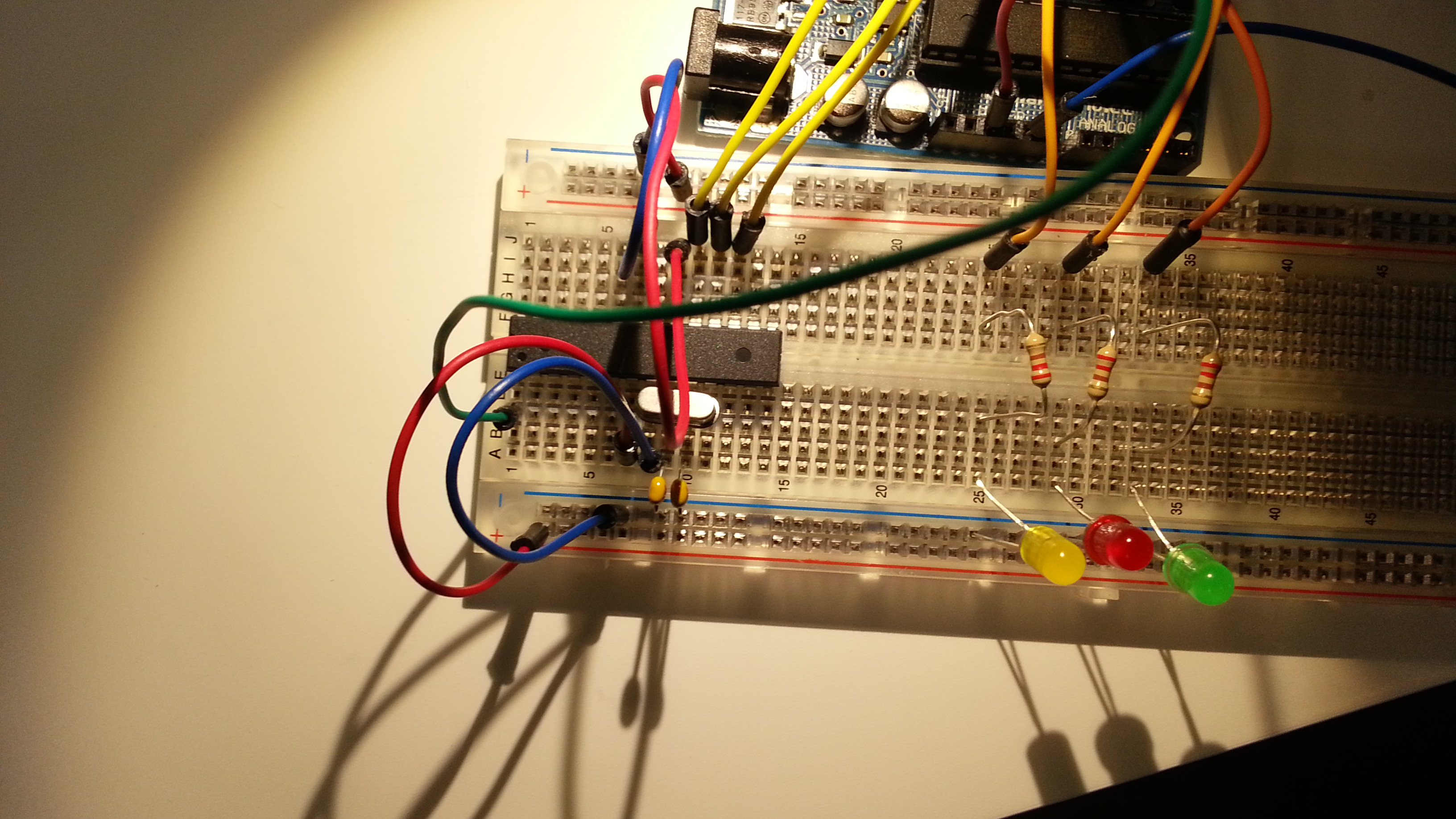
Now for the example. Let’s get the wiring done first. I hooked up three LEDs each has a 200 ohm resistor and then connected to ground. The positive pin of the LED I have hooked up to pin 7 for green, pin 6 for white/blue, pin 5 for red. I originally tried pin 2, but this pin is used by the WiShield and would not work. (That is the other piece of critical information that I needed from the eBay listing, which pins are being used.)
Now here is the code for the project, (minus all the security information for my network):
/* * A simple sketch that uses WiServer to serve a web page */
// setup the wireless mode // infrastructure – connect to AP // adhoc – connect to another WiFi device unsigned char wireless_mode = WIRELESS_MODE_INFRA;
unsigned char ssid_len; unsigned char security_passphrase_len; // End of wireless configuration parameters —————————————-
int redState = 0; int whiteState = 0; int greenState = 0;
int redPin = 5; int whitePin = 6; int greenPin = 7;
// This is our page serving function that generates web pages boolean sendMyPage(char* URL) { if (strcmp(URL, "/red") == 0) redState = !redState; if (strcmp(URL, "/white") == 0) whiteState = !whiteState; if (strcmp(URL, "/green") == 0) greenState = !greenState; digitalWrite(redPin, redState); digitalWrite(whitePin, whiteState); digitalWrite(greenPin, greenState); // Check if the requested URL matches "/" // if (strcmp(URL, "/") == 0) { // Use WiServer’s print and println functions to write out the page content WiServer.print("<html>"); WiServer.print("Light Control<br><br>"); printLightStatus("red", redState); printLightStatus("white", whiteState); printLightStatus("green", greenState); WiServer.print("The page you requested was: "); WiServer.print(URL); WiServer.print("<br>The arduino has been running for: "); WiServer.print(millis()); WiServer.print(" milliseconds<br>"); WiServer.print("</html>"); // URL was recognized return true; //} // URL not found return false; }
void setup() { // Initialize WiServer and have it use the sendMyPage function to serve pages WiServer.init(sendMyPage); // Enable Serial output and ask WiServer to generate log messages (optional) Serial.begin(57600); WiServer.enableVerboseMode(true); pinMode(redPin, OUTPUT); pinMode(whitePin, OUTPUT); pinMode(greenPin, OUTPUT); }
void loop(){
// Run WiServer WiServer.server_task(); delay(10); }
Several other things to note. On the board it says “Copperhead WiFi Shieldâ€. However, on the net, it is referred to only as “CuHead Wifi Shieldâ€. (Cu being the atomic symbol for Copper. This was very frustrating, as I could not find any information about the Copperhead Wifi Shield…. Lots of stuff on Copperheads but nothing related to WiFi or Arduinos 🙂 ). Also, it has the link www.linksprite.com on the board, but I found the AsyncLabs.com to be the place to get my answers.
If you find a cheaper place to get the WiShield, please leave a comment and let me know. It would open up a whole lot more possibilities if it was possible to get WiFi connectivity in the $20 range.
Also, if you know some really cool projects using the WiShield, let me know that too.