1.09 Other signals and 1.10 Logic Levels

Let’s cover two sections today:
1.09 Other signals
1.10 Logic Levels

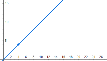
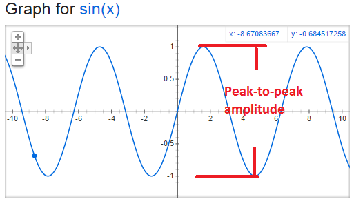
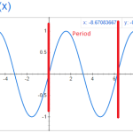
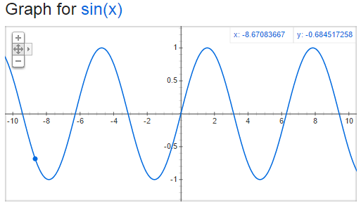
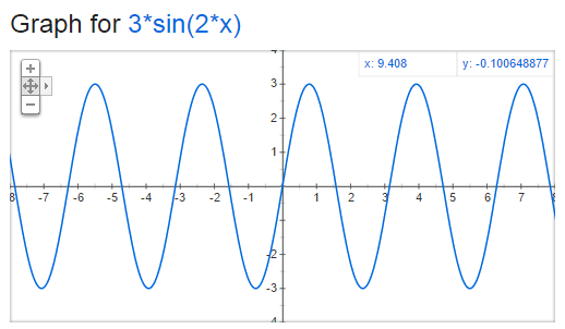
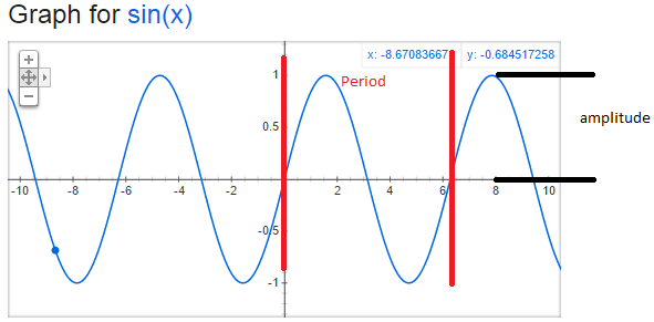
We have been looking at Voltage as a function of time and seeing how it will look on a graph.  The past few days we have talked about graphs that are sine wave.

sinewaveDifferent2

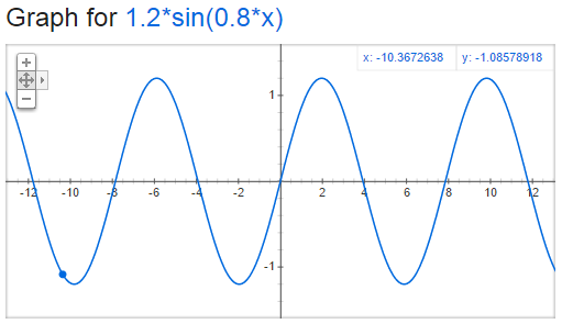
But there could be other ways that this could look too.  Consider if voltage started out at zero and continued to increase.  It would look something like this:

ramp

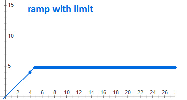
But it is not possible to increase voltage indefinitely and so the graph would really look like this:  (Ramp with limit)

rampWithLimit

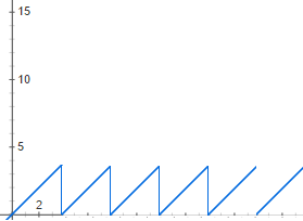
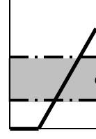
But there are other interesting graphs to.  Consider the case of voltage increasing to a point, and then when it reaches a certain point it goes to zero and then begins again.  Let’s say you have a circuit that triggers at a certain voltage, and a capacitor that you are charging up till that point.  It might looks something like this sawtooth wave:

sawtoothwave

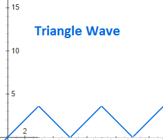
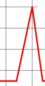
But you can also imagine a case where it reaches a point and decreases at the same linear rate.  This would look like a triangle wave:

trianglewave

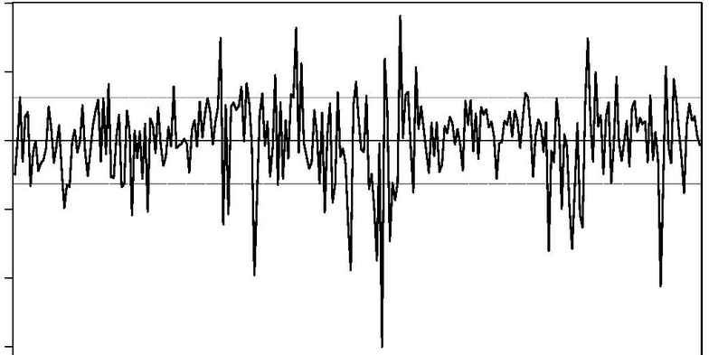
And then there is noise, a complex, background static that we always need to consider and usually minimize:
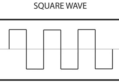
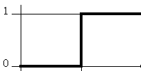
noise

Square waves

squareWave

Steps

step

Spikes

spike

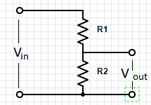
But in digital electronics we concern ourselves with logic levels and interrupting a particular voltage as either a true or a false; as a on or a off; as a 1 or 0.  Most digital electronics have a threshold voltage.  Above that voltage it is considered to be true/on/1.  Below that voltage it is considered to be false/off/0.

LogicLevel


1.08 Signal amplitudes and decibels

Peak-to-peak amplitude (pp amplitude) is twice the amplitude. This is the measurement of the amplitude from the bottom peak to the top peak as illustrated below:
sine-wave-pp-amplituded


root-mean-square amplitude (rms amplitude) has different formulas based upon the shape of the signal.  For sine waves only it is given by:

sinewave-rms

Decibels is a comparison between two signals.

When comparing amplitude use this formula:

decibels-amplitude


When comparing the power use this formula:

decibels-power


Sometimes decibels are presented as units.  This is because their is an implicit signal that is being used for comparison.  Here are some common ones:

a) dBV:  1 volt rms

b) dBm – the voltage corresponding to 1mW with an assumed load impedance

c) small noise generated by a resistor at room temperature


1.07 Sinusoidal signals

The next few sections in The Arts of Electronics deals with signals.  What are the characteristics of signals?  Amplitude, frequency, shape, etc.

The values we are looking at is voltage as a function of time.  The most basic signal is the sinusoidal signal.  Have you ever graphed y=sin(x) and end up with:

sine-wave


But how would you compare this wave to the following:

sinewaveDifferent1

sinewaveDifferent2


There are two key things to think about when comparing sine waves:  frequency and amplitude.    The amplitude is the distance from y=0 to the top of the sine wave.  The frequency is how many times the wave repeats in a given period of time.  We typically use the unit hertz (Hz) for frequency, which is one cycle (or period) per second.  Lets take a look at period and amplitude in our original sine graph:

sinewaveWithAmplitudeAndPeriod

The formula that you should remember is

V=A*sin(2*pi*f*t)

A is the amplitude in volts, f is the frequency in Hz and t is the time in seconds.


1.06 Small-signal resistance

Ohm’s law is R=V/I.  For the ordinary resistance, this is a constant proportion for a large range of V.  But this is not true for all devices.  Today we look at the Zener diode which has a high resistance up to a point and then almost no resistance for a large range of V.  Also, we look at the tunnel diode (also known as the Esaki diode) which actually has a negative resistance over a particular range of V.


1.05 Thevenin’s equivalent circuit

Any two terminal network of voltage sources and resistors can be replace by a single voltage source in combination with a single resistor.  This is called the Thevenin’s equivalent circuit:

thevenins-equivalent-circuit


The first step is to identify the two terminals of the network.

Then to figure out Rth, replace any voltage sources with short circuits and any current sources with open circuits.

Calculate the voltage between the two terminals.

Then figure out Vth between the two terminals.

To figure this out using testing and measuring, it is only necessary to find the voltage at the two terminals with power on, and the resistance with power off.

This can greatly simplify circuit analysis of complex circuits.

Check out videos on YouTube with more detailed information:

www.youtube.com/results?search_query=thevenin+equivalent+circuit


1.04 Voltage and current sources

Let’s take a look at the symbols for voltage sources and current sources. Also, let’s discuss the properties of the ideal voltage source and the ideal current source.

The ideal voltage source will maintain the same voltage between its terminals regardless of the load. This is easiest with an open circuit but becomes impossible with a short circuit.

The ideal current source will maintain the same current regardless of the resistance of the load. This is easy with an open circuit but becomes more and more difficult as the resistance increases.


1.03 Voltage Dividers

Voltage Dividers take an input voltage and gives you a smaller, fractional output voltage. This can be useful for volume control or when interfacing between logic circuits that run at 5V with new/lower power devices that run at 3.3V.

A voltage divider is a simple circuit made up of only two resistors (R1 & R2 in the diagram below).
voltage-divider


voltage-divider-formula

1.02 Relationship between voltage and current: resistors

Art of Electronics 2nd Edition p 4-7

What you MUST learn

Resistance (represented in formulas as “R”) measured in Ohms which is represented using the symbol:

ohm

Resistance is the relationship between Current (I) and Voltage (R).

This relationship is defined by Ohm’s law:  R = V/I.

Circuit diagrams represent resistors as

resistor


Resistors in Series: (Always bigger)seriesResistor

R= R1 + R2


parallelResistor
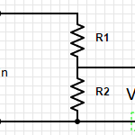
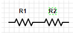
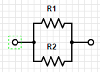
Resistors in Parallel: (Always smaller)

R = (R1*R2)/(R1+R2)


Shortcut #1:

A large resistor in series with a small resistor has the resistance of the larger one, roughly.

A large resistor in parallel with a  small resistor has the resistance of the smaller one, roughly.


Try to develop an intuitive sense of the voltage and current in the parts of the circuit.  Do not try to calculate to be extremely precise because the precision of the components will make this pointless.  Also, good circuit design should be tolerant of variations.


Power:

P=IV

Using Ohm’s law you get:

P=(I^2)R

P=(V^2)/R


Things good to learn

The inverse of resistance is conductance (represented by “G” in formulas)  G=1/R

Restatement of Ohm’s law:  I=GV

Conductance is measured in siemens

Siemens

siemens is also known as mho (ohm spelled backwards)


1.01 Voltage and Current

Art of Electronics 2nd edition, pages 2-4

Overview

Voltage & Current describe two aspects of electronic circuits that are fundamental to understand and on which everything else will build on.

What you MUST learn

Voltage refers to a force that when applied across a circuit causes current to flow.  Voltage is measured in volts (using the symbol V) also called a “potential difference”.  It is measured across two points in a circuit.  A joule of work is needed to move a coulomb of charge through a potential difference of one volt. A coulomb is the charge of about 6×10^18 electrons.

Current (symbol: I) is the measure of electronics through a point in a circuit.  It is measured in amperes (amps) (symbol: A).  1 ampere (amp) is 1 coulomb of charge passing through a point per second.


Conservation of Charge:  Kirchhoff’s current law

The sum of currents into a point or node is equal to the sum of the currents out of a point or node.  This is referred to as Kirchhoff’s current law.


Kirchhoff’s voltage law

The sum of voltage drops through one branch of a circuit will equal the sum of voltage drops across the other branches of the circuit.


P=VI

Power (work per unit time), measured in watts.  (1 W = 1 J/s)

P=VI = (work/charge) x (charge/time) = work/time

P=VI= (1 joules/1 coulomb) x (1 coulomb/1 second) = 1 joules/second = watt.


Things good to learn

Voltage is usually written with the symbol V but sometimes E is used.   Voltage is also called a “potential difference” or electromotive force (EMF).


Prefixes:

Multiple Prefix Symbol
10^12 tera T
10^9 giga G
10^6 mega M
10^3 kilo k
10^(-3) milli m
10^(-6) micro µ
10^(-9) nano n
10^(-12) pico p
10^(-15) femto f


When abbreviating a unit with a prefix, the unit follows the multiplier with no space and the unit is capitalized.  However, no capitalization for both prefix and unit when spelled out.  1mW = 1 milliwatt

1 MV = 1 megavolt


Related information and insights from my other books

Introductory Circuit Analysis 9th edition – chapter 2

Structure of the atom:

nucleus is made up of protons (that have a positive charge) and neutrons that have a negative charge.  The proton and neutron are relatively the same mass.  But the electron is considerably smaller (1836 times smaller) than the proton but has a negative charge that is equal to the positive charge of the proton.


Other things of interest


If you need more help

Voltage


Current


Joule


If you wanted to know

Who defined:

Voltage

Volt

Current

amp

joule

watt

multiplier prefixes


People who contributed:

Watt

Power Point:
GadgetNateJourneyThroughArtOfElectronics-01.01-VoltageAndCurrent

Preparing for my journey through “The Art of Electronics”

2014-12-28 23.17.30-2
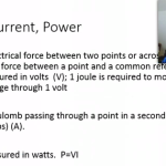
“The Art of Electronics” by Horowitz and Hill is the definitive guide to Analog and Digital electronics.  I had bought the 2nd edition over a decade ago, with the intention of going through it.  But this year is going to be the year.  And I am hoping that you will help me.

My plan is to go through a section a day, and to write a short blog post summarizing what I learned.  I have collected several electronics books, and I plan to make reference to them as I go on this journey.  These include:

In addition to a brief summary of what I learn from that section, I plan to create a video post, create additional exercises, and assemble related circuits.  I am hoping that it will be an exciting adventure, and that by having to produce a daily blog post, I will have the discipline to see it through.  And should I stumble, hopefully an encouraging comment or email from you will nudge me back on the path.

First thing is that I need some help by those that are familiar with Electronics.  I am an Amateur with hopes of achieving proficiency.  I do not want my struggles to cause problems for others following along.  Therefore, I would like to have someone knowledgeable review my notes before I publish them on this blog.  If you would be willing to help out, then please email me at nathan.price@gmail.com.  Let me know how much you would be willing to help out.  I figure each blog post would take 15 minutes or so to review.   I would like to give you credit for reviewing, but if you want to remain anonymous, then that is fine too.

Second, if you want to join this adventure, then sign up for email notifications as we get ready to start this journey, and then for updates as the journey begins:

Enter your email address:

Delivered by FeedBurner

 I am already on the journey, but I do not plan to start publishing them till February 1, 2015.  This will give me a chance to have them reviewed, and will give me a little buffer.

Also, I plan to create a lot of circuits and do demonstrations.  If you have some extra components that you can donate to me, that would be great!  Email me at nathan.price@gmail.com with the details.  Also, if you are interested in supporting this journey financially, then donations would be welcomed.  (I converted my PayPal to a commercial account some years back, and it seems it can’t be converted back.  So the donations would say that were to ISpeakHindi.com, which is another website created with the same idea of having to commitment of studying each day.  That site was semi-successful as now I can read/write/speak/understand basic Hindi…)

For now, go ahead and order the book so that you can join along…