arduino-info.wikispaces.com/Nrf24L01-2.4GHz-HowTo
The VexIQ robot system seems to have several advantages over the Lego Mindstorm.
1) Price: VexIQ super kit is only $299.99 and contains the following:
The Super Kit is an all-encompassing introduction to STEM and robotics. Students can use the familiar handheld Controller to drive robots right out of the box or program them to run autonomously using the additional Smart Sensors. While the included Clawbot IQ instructions help students easily build their first robot, the intuitive snap-together parts mean the sky is the limit for their VEX IQ creations.

The Lego Mindstorm kit is about the same price, but limits you to 4 sensors and 4 motors. The VexIQ will let you hookup 12 of either. Also, there are a lot more gears and drive chain options that will allow for a wide variety of robots to be built:


You can program it in RobotC or using a graphical environment similar to Scratch called ModKit.
This looks like a good way to get into the quad copter/first person camera/display hobby. Everything you need in one box for less than $400.
www.horizonhobby.com/nano-qx-fpv-rtf-with-safe-technology-blh7200
Amazing Ultra Micro Quad
The tiny Blade® FPV Nano QX quadcopter is a totally immersive RC experience you can take everywhere. Incredibly light and surprisingly durable, the FPV Nano QX can be flown in spaces no bigger than an office cubicle. Its potent motors are smooth and Spektrum™ 2.4GHz DSMX® radio technology delivers outstanding 4-channel maneuverability. But it’s the exclusive SAFE® technology built-in that offers a quadcopter experience like no other. That’s because the specially tuned SAFE system makes sophisticated flight envelope protection possible so flying is incredibly easy and more fun-even if it’s your first time. Plus, the Spektrum™ ultra micro FPV camera is already installed which means you can get started in the short time it takes to charge the batteries.
SAFE™ Technology
The Blade® FPV Nano QX features Horizon Hobby’s newest innovation in RC flight, SAFE® technology. This revolutionary system optimizes the FPV Nano QX for precision hovering and accuracy in two flight modes.
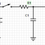
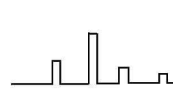
This is an example of a differentiator. Send a signal in, and the signal you get out will be just the edges of the wave form. If the input signal is a square wave, then the output will be a series of spikes at each of the sides of the square wave
Incidentally, having a wave that includes spikes could indicate that you have unintentional capacitive coupling.
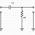
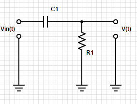
Let’s look at how voltage (V) and current (I) change with respect to time in circuits with capacitors and resistors.
Take a look at this circuit:
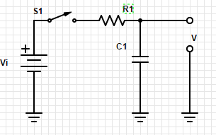
Close the switch S1 connecting the capacitor (C1) to the battery (Vi) through resistor (R1). How fast will C1 charge?
That is determined by the relationship between R1 and C1. It is known as the RC time constant.
Assuming that C1 = 1 microfarad and R1 = 1k ohm, then the time constant will be 1. And we have a shortcut that it will be within 1% of the input voltage with in 5RC, so within 5 seconds.
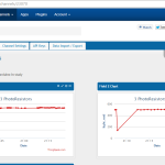
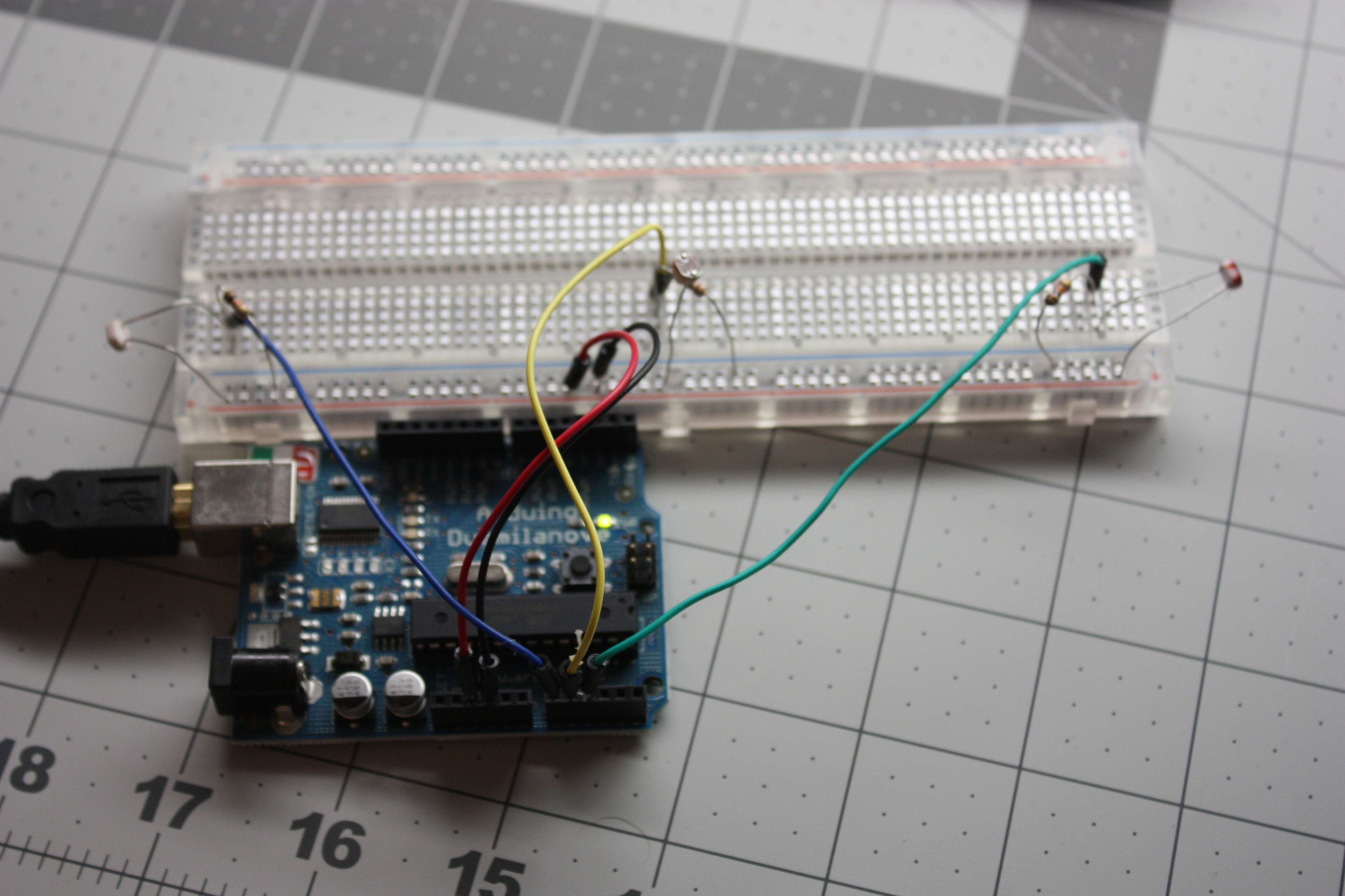
I have three photoresistors in my study that are measuring light coming from 3 directions and showing the live and historical data on the graphs below.
How did I do it?
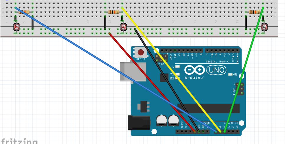
Simple circuit. Here is how the Arduino is hooked up. (The resistors are 10k.)
/* Simple test of the functionality of the photo resistor
Connect a resistor (around 10k is a good value, higher
values gives higher readings) from pin 0 to GND. (see appendix of arduino notebook page 37 for schematics).
—————————————————-
PhotoR 10K
+5 o—/\/\/–.–/\/\/—o GND
|
Pin 0 o———–
Similar setup for Pin 1 & Pin 2.
—————————————————-
*/
int lightLeftPin= A0;
int lightMidPin =A1;
int lightRightPin = A2;
int lightLeft, lightMid, lightRight;
void setup()
{
Serial.begin(9600); //Begin serial communcation
}
void loop()
{
lightLeft = analogRead(lightLeftPin);
lightMid = analogRead(lightMidPin);
lightRight = analogRead(lightRightPin);
Serial.println(“###BOD”);
Serial.print(“light_right,”);
Serial.println(lightRight);
Serial.println(“###EOD”);
delay(15000);
Serial.println(“###BOD”);
Serial.print(“light_mid,”);
Serial.println(lightMid);
Serial.println(“###EOD”);
delay(15000);
Serial.println(“###BOD”);
Serial.print(“light_left,”);
Serial.println(lightLeft);
Serial.println(“###EOD”);
delay(15000);
}
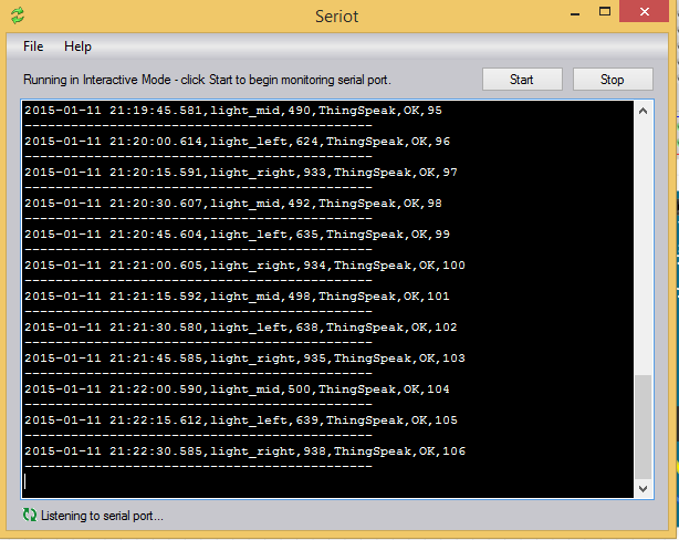
I then setup an account at ThingSpeak.com
And to connect the arduino to the internet I used my laptop and a program called Seriot. It can be downloaded from:
This program will listen to the serial port and write the data to ThingSpeak.com
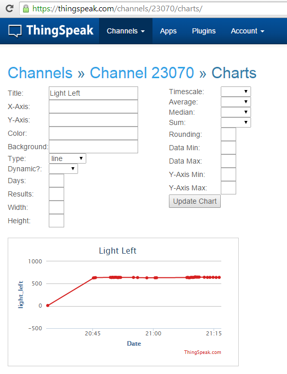
You can then use Restful API calls to get to the data and to chart it.
They have a nice ChartEditor
thingspeak.com/channels/23070/charts/
Capacitors hold charge. Capacitors do not conduct.
We measure capacitance in farads and charge in coulombs (equivalent to the charge 6×10^18 electrons).
a capacitor with 1 farad of capacity will charge 1 coulomb of charge after 1 volt has been applied across its terminals for 1 second.
Q=CV
The capacitor is basically plates of two conductors separated by a non-conductor. When a voltage is applied, the charge accumulates. And when the voltage has been removed, then it can release that charge.
I found this really cute video that explains a capacitor:
The total capacitance of capacitors in parallel is the sum of the capacitors.
Ctotal = C1+C2+C3…
Capacitors in parallel will always result in a BIG capacitance.
However capacitors in series will always result in a smaller capacitance. Two capacitors in series have the capacitance of:
Ctotal = (C1C2)/(C1+C2)
Capacitors in series will always result in a capacitance smaller than the smaller capacitor.
Since capacitors do not conduct current, they do not dissipate power.
<iframe src=”http://prezi.com/embed/i1psv7u6nfbl/?bgcolor=ffffff&lock_to_path=0&autoplay=0&autohide_ctrls=0&features=undefined&token=undefined&disabled_features=undefined” width=”550″ height=”400″ frameBorder=”0″ webkitAllowFullScreen mozAllowFullscreen allowfullscreen></iframe>
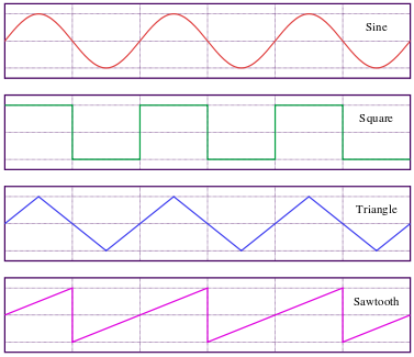
There are a variety of test equipment that can create signals with ranges of different characteristics. Three classes of these signal sources we will talk about today: Signal Generators, Pulse Generators, and function Generators.
Signal Generators produce sine waves while allowing you to define the amplitude, frequency, and even allowing for these to vary overtime.
Pulse Generators create pulses, allowing for you to vary the amplitude, pulse width, frequency, and even rise time and fall time.
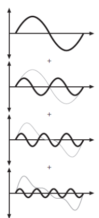
Function Generators allow for you to create more complex waves, in a variety of shapes: