arduino-info.wikispaces.com/Nrf24L01-2.4GHz-HowTo
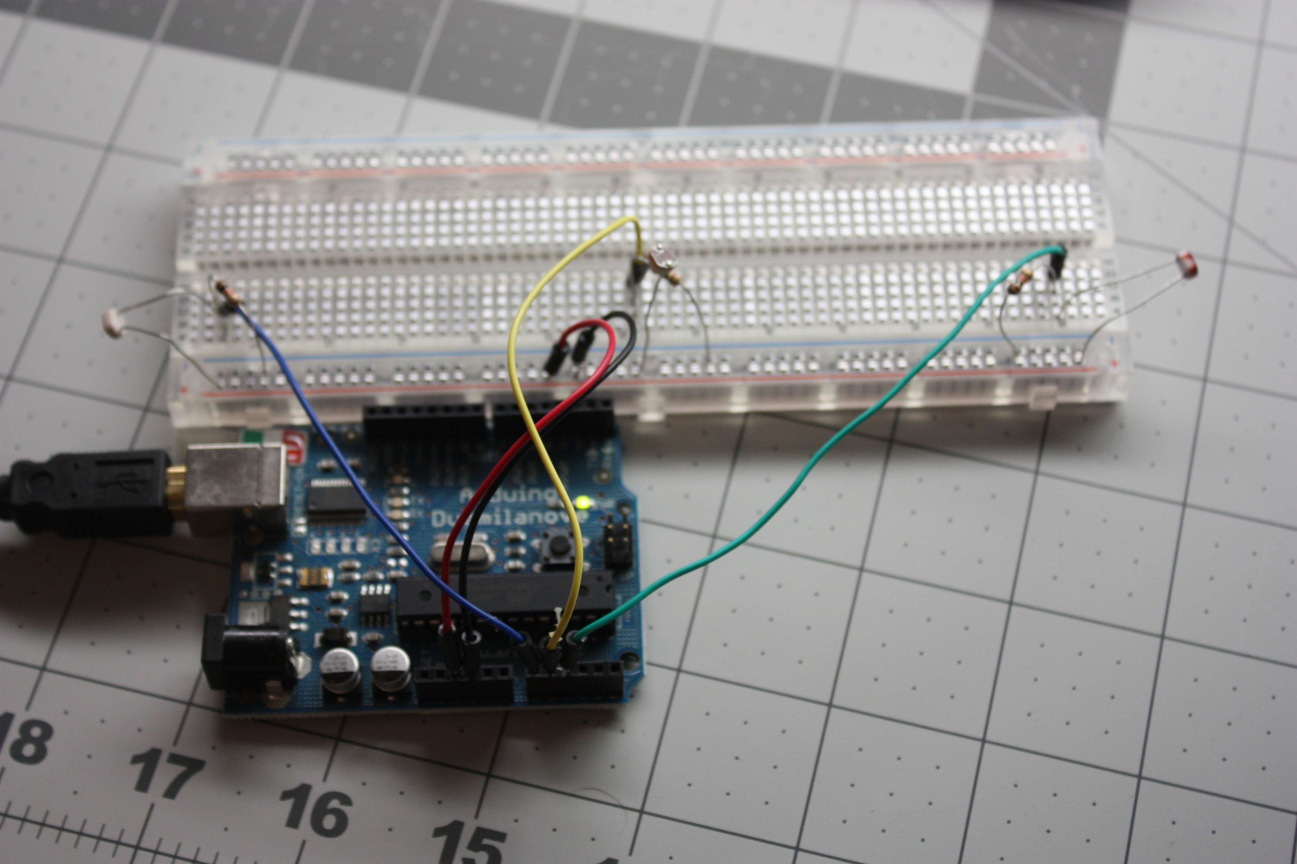
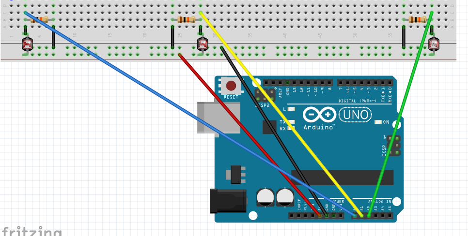
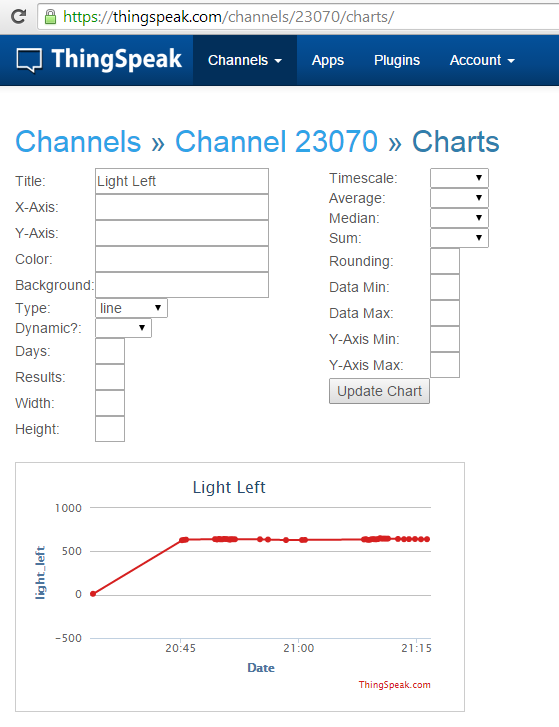
I have three photoresistors in my study that are measuring light coming from 3 directions and showing the live and historical data on the graphs below.
How did I do it?
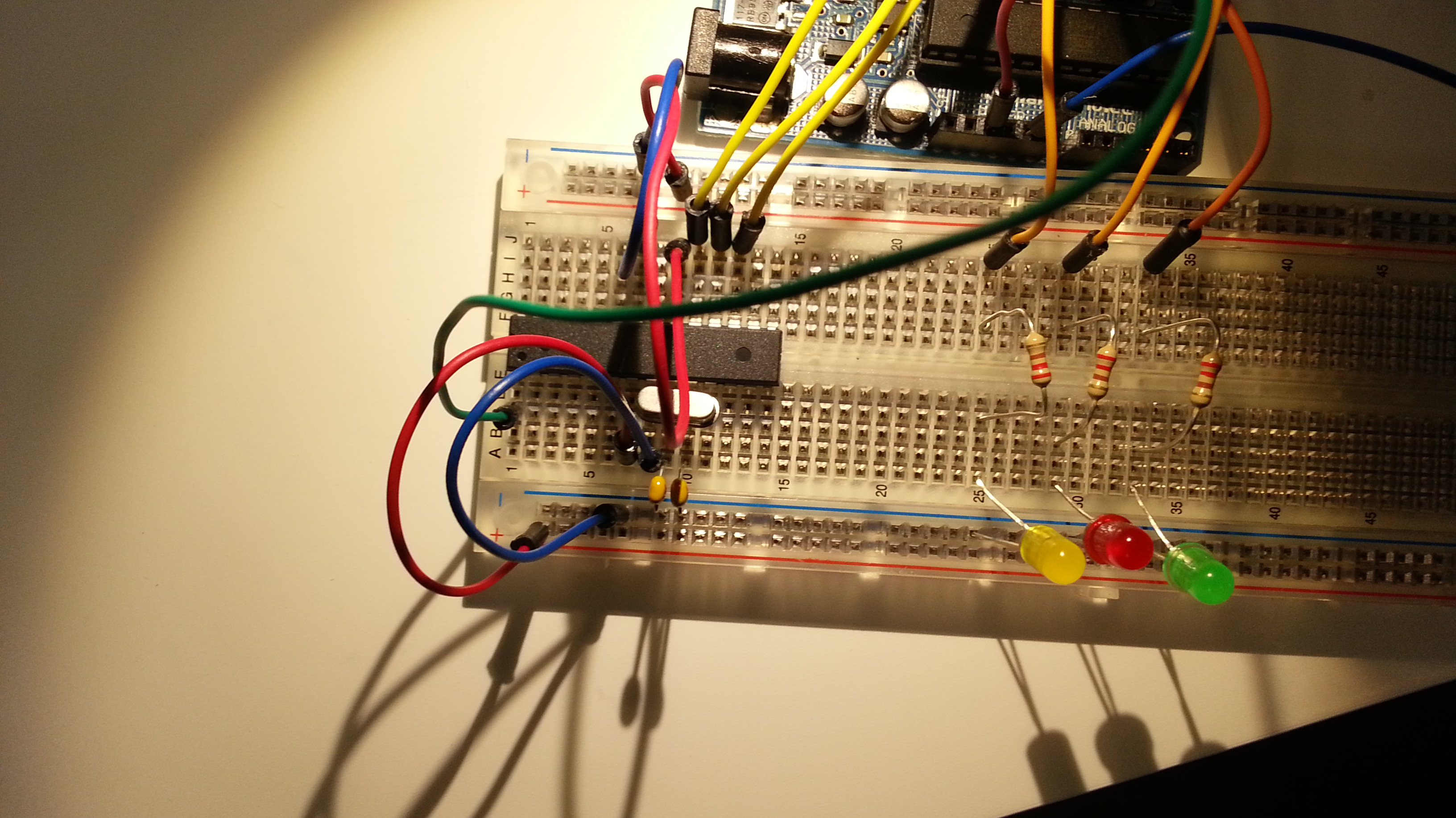
Simple circuit. Here is how the Arduino is hooked up. (The resistors are 10k.)
/* Simple test of the functionality of the photo resistor
Connect a resistor (around 10k is a good value, higher
values gives higher readings) from pin 0 to GND. (see appendix of arduino notebook page 37 for schematics).
—————————————————-
PhotoR 10K
+5 o—/\/\/–.–/\/\/—o GND
|
Pin 0 o———–
Similar setup for Pin 1 & Pin 2.
—————————————————-
*/
int lightLeftPin= A0;
int lightMidPin =A1;
int lightRightPin = A2;
int lightLeft, lightMid, lightRight;
void setup()
{
Serial.begin(9600); //Begin serial communcation
}
void loop()
{
lightLeft = analogRead(lightLeftPin);
lightMid = analogRead(lightMidPin);
lightRight = analogRead(lightRightPin);
Serial.println(“###BOD”);
Serial.print(“light_right,”);
Serial.println(lightRight);
Serial.println(“###EOD”);
delay(15000);
Serial.println(“###BOD”);
Serial.print(“light_mid,”);
Serial.println(lightMid);
Serial.println(“###EOD”);
delay(15000);
Serial.println(“###BOD”);
Serial.print(“light_left,”);
Serial.println(lightLeft);
Serial.println(“###EOD”);
delay(15000);
}
I then setup an account at ThingSpeak.com
And to connect the arduino to the internet I used my laptop and a program called Seriot. It can be downloaded from:
This program will listen to the serial port and write the data to ThingSpeak.com
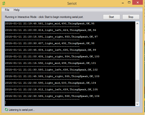
You can then use Restful API calls to get to the data and to chart it.
They have a nice ChartEditor
thingspeak.com/channels/23070/charts/
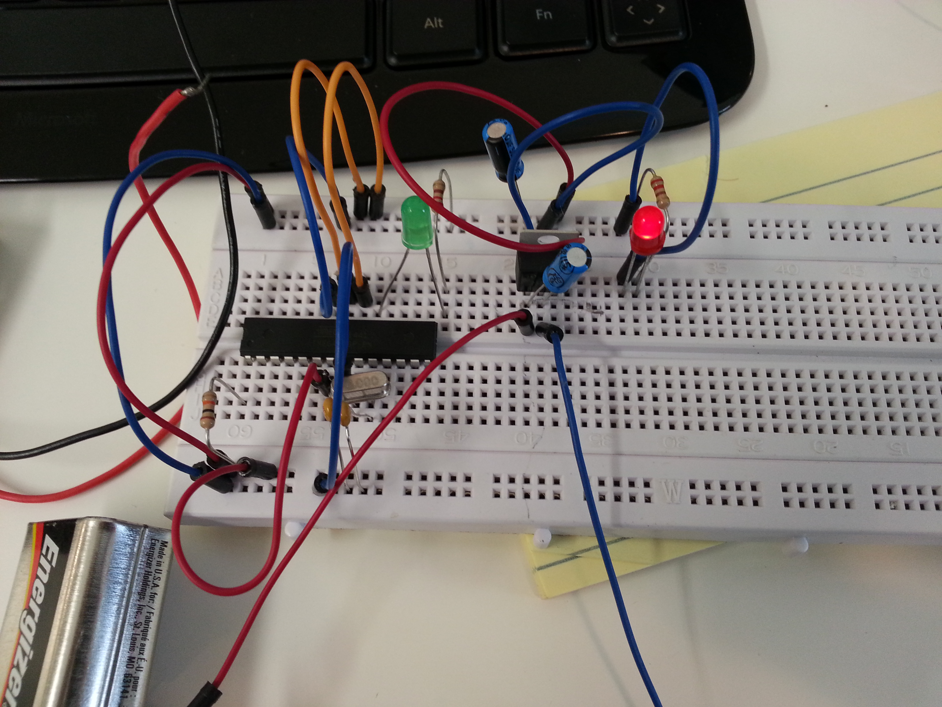
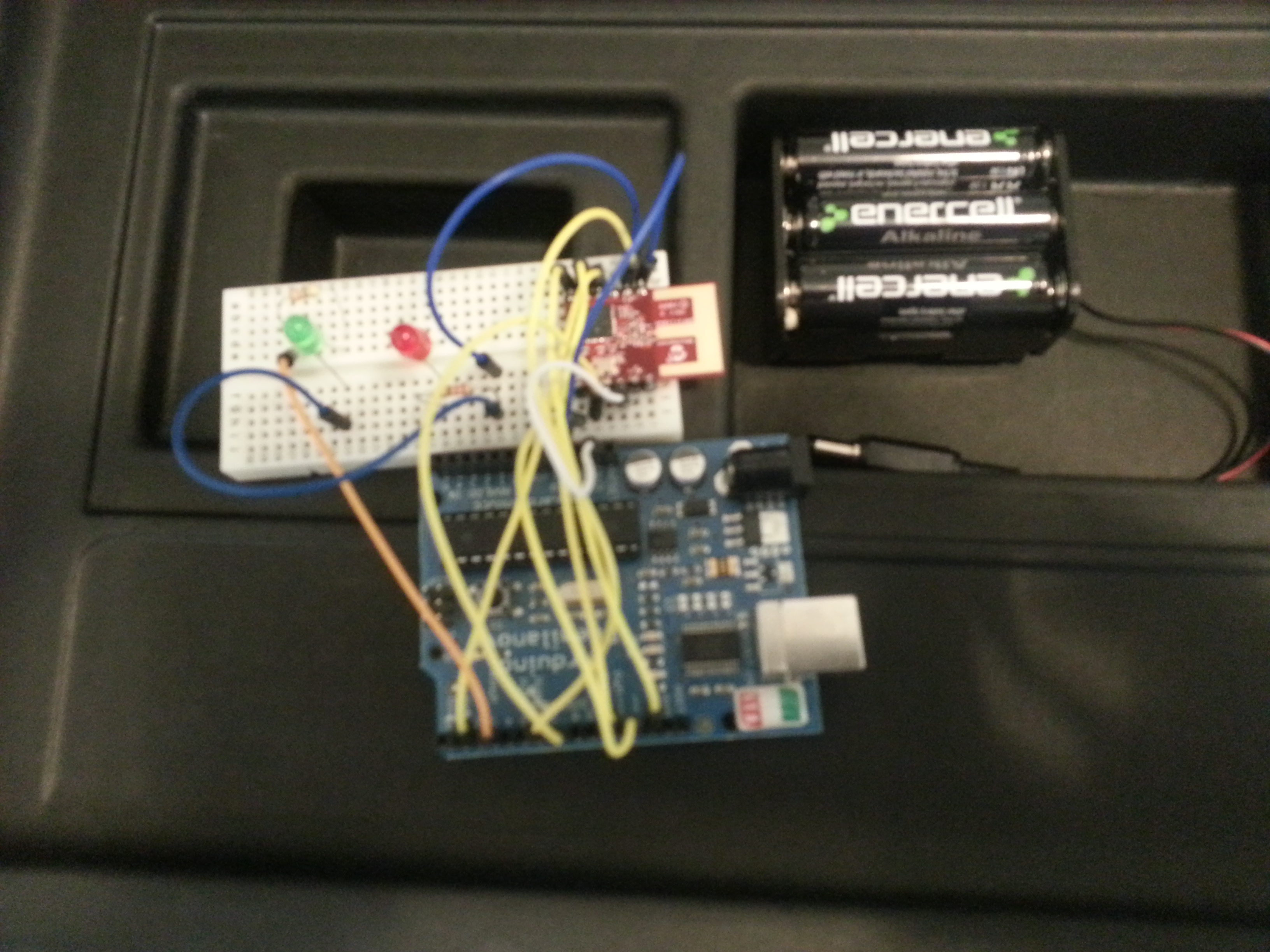
Two accomplishments today. First, I was able to use the Atmel 328P chip outside of the Arduino board. What is the benefit of this? First, cost.. The Arduino UNO is currently $25 but the Atmel 328P is only $1,86 if you buy it on eBay, and only a few dollars more if you buy it from some place else. However, you are going to need a few more components such as a 16MHz crystal, a few capacitors, resistors, voltage regulator, wires, and something mount it on.. All told, probably another $5. Now you won’t have the nice board, the USB to serial converter, the 3.3volts power connection (could easily use two resistors to create a voltage divider to step the 5V down). So it is not an apple to apple comparison. But if you want to have these chips in a lot of little projects, then you are going to have a lot more options when the price gets to the $5-$10 range instead of the $25 range.
Also, you can compact the design down to just what you need. You have more control over the final form factor. And this is also a good step into the world of microcontrollers in general. Before you know it, you will be programming the entire Atmel family of chips..
So, how to get started. There were a number of really good tutorials that I looked through.:
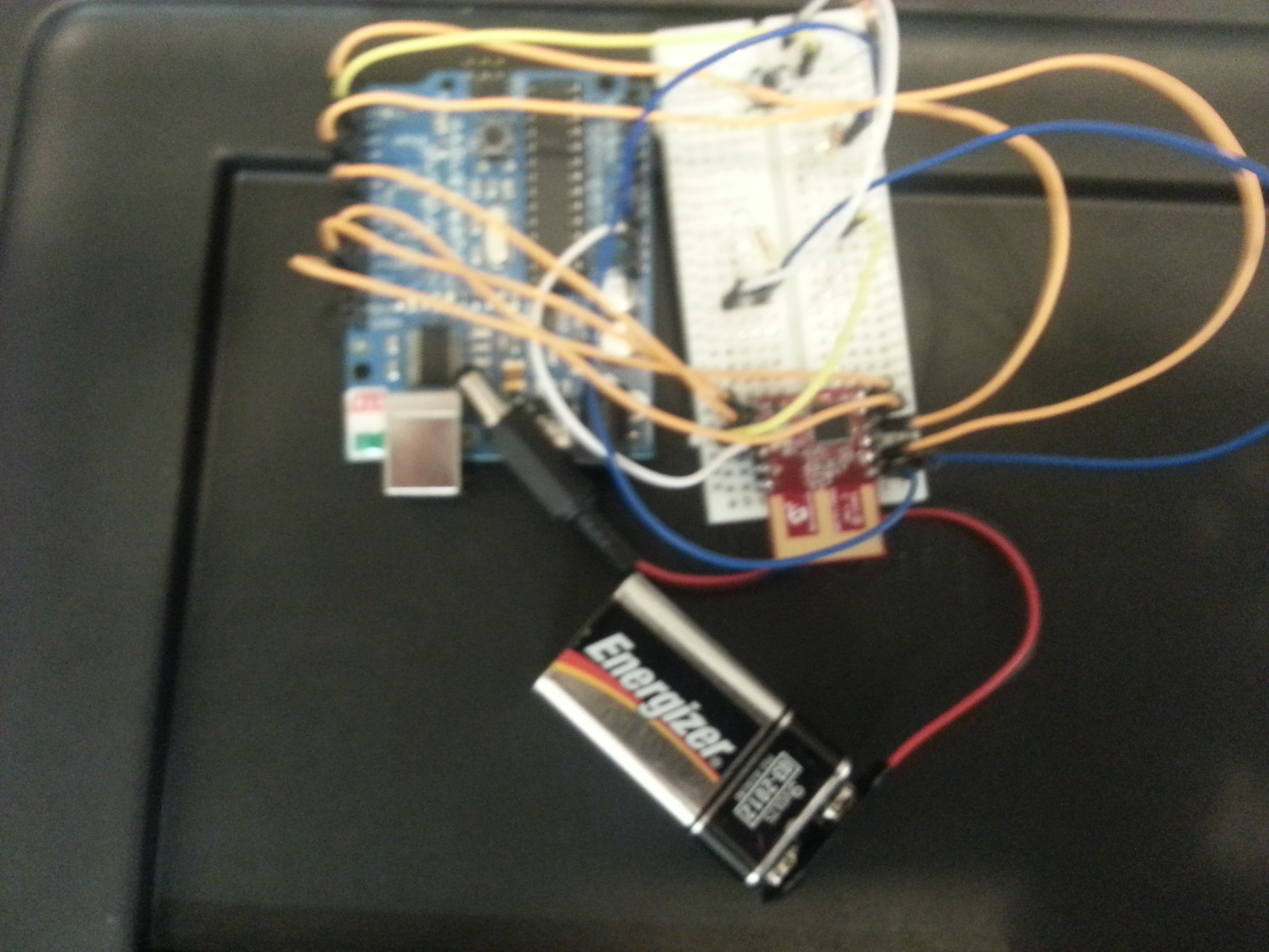
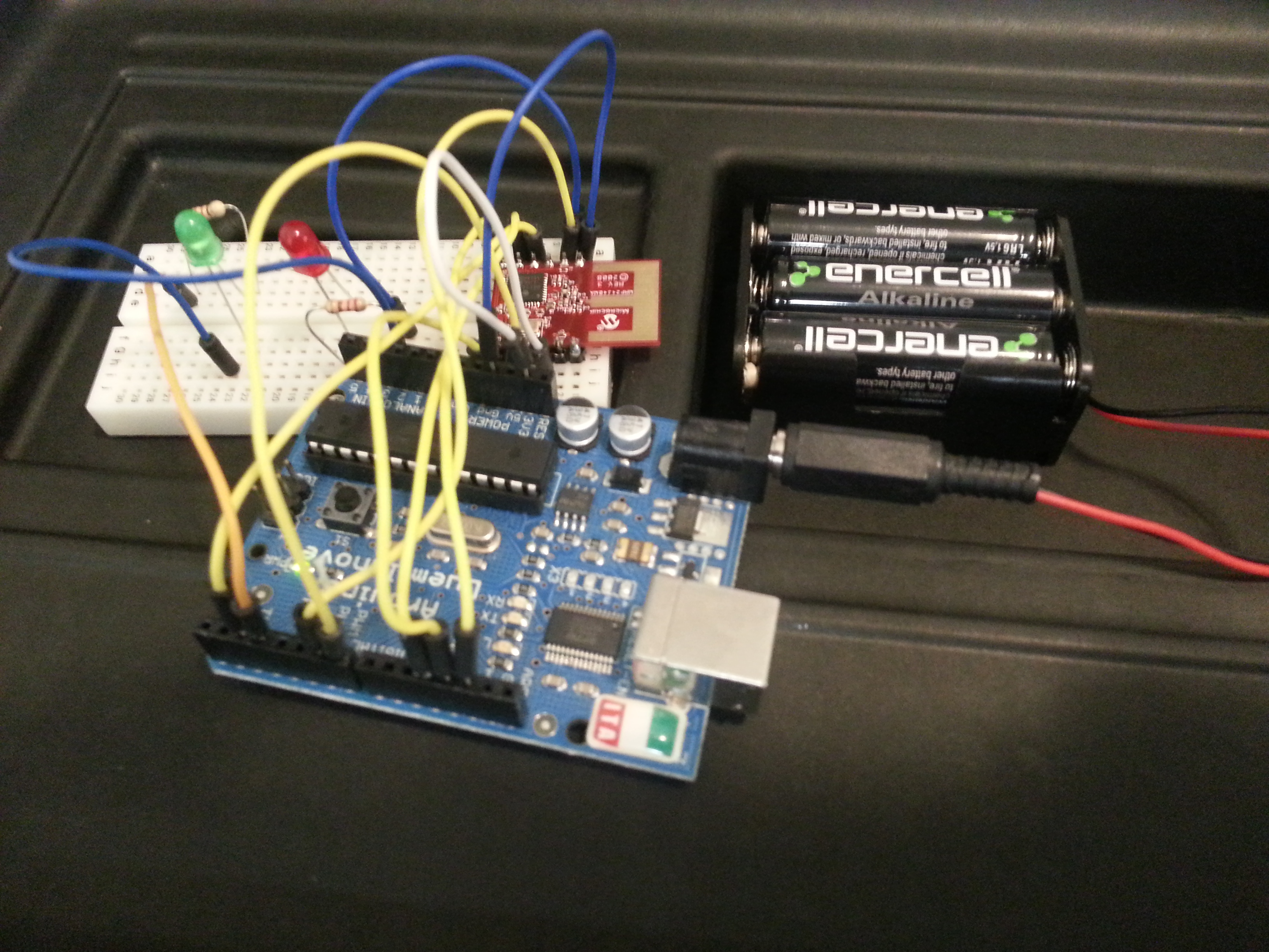
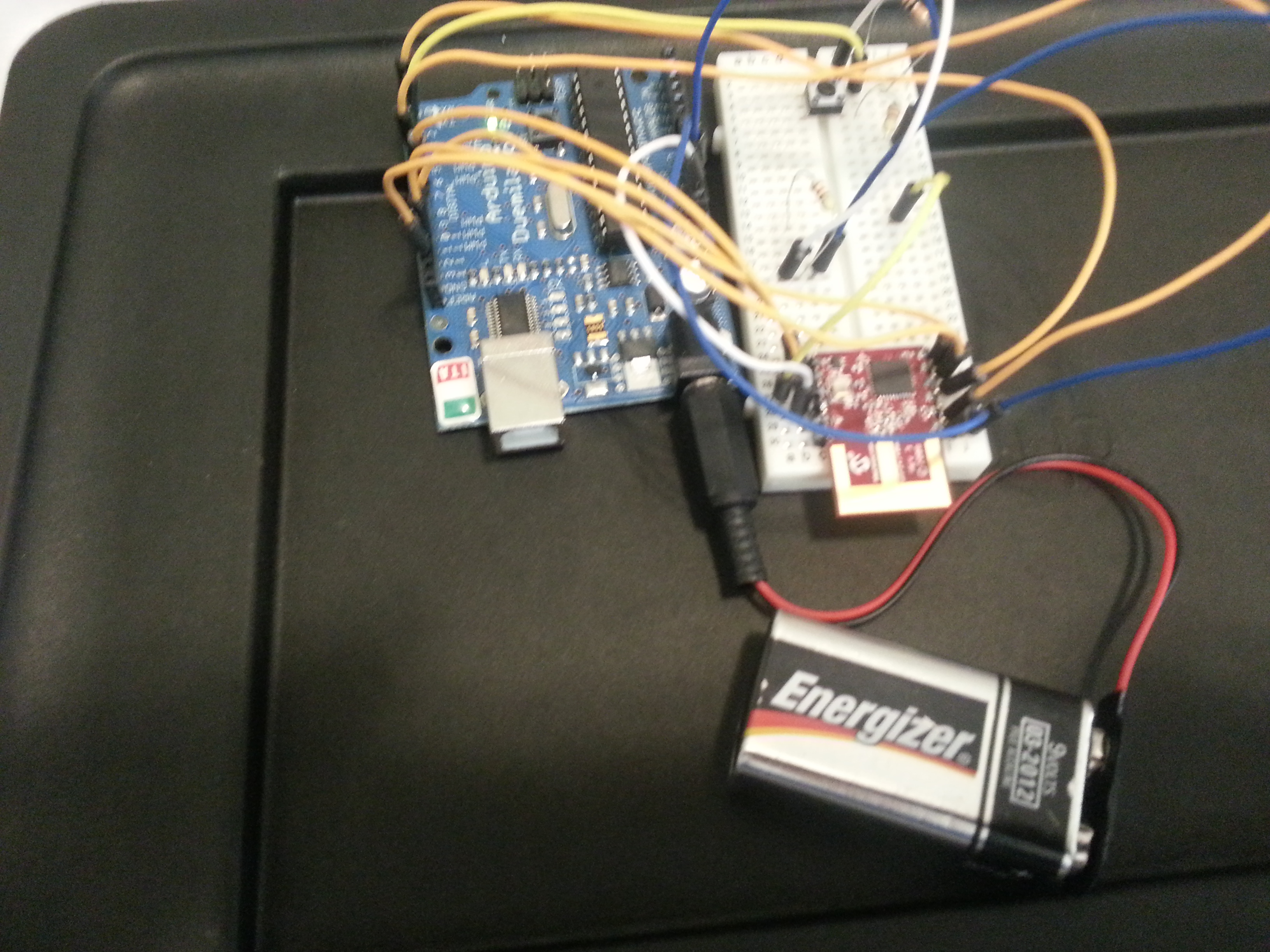
Here is some more info about the module and how to use it:
Data Sheet” (DS39776)http://ww1.microchip.com/downloads/en/DeviceDoc/39776C.pdf
My youngest son has thousands of Magic cards that he wants to scan. Instead of doing it manually, I thought it would be good to create a simple device to take a picture, move the card from the top, take a picture, etc.
Here you can see one of the early iterations of it actually working. It uses a PC cooling fan to pick up the top card. There is a light sensor on the bottom of the fan that is used to determine if the fan is in contact (and remains in contact) with the fan. There is one servo that moves it up and down, and another that moves it left and right. An arduino is used to control the fan and servos and monitor the light sensor. This is hooked up to a laptop that has a simple Python program running on it that uses the libraries from OpenCV to take the picture. The Python program communicates with the Arduino via the serial port.
Here is a video of it in action:
This was created a few weeks ago. It took about 20 hours of experimentation, but it has scanned hundreds of cards. There is quite a bit more work to be done on it to make it work as well as we would like.
Teaching kids the basics of electronics and programming is something that I have been working on doing through my GadgetCamps. Â The GadgetCamps is 100% hands on. Â Hooking up circuits, typing in code, seeing how things work. Â There are many ways to make things “hands on”. Â The TeleScrap Book takes a unique approach. Â And it is Arduino based!
TeleScrapbook from Natalie Freed on Vimeo.
More information available from:
Last week we had 6 middle school students at our first GadgetCamp. That was just the perfect number of students for the space at the Mathnasium that we are using.
The kids learned many things. How to identify the parts in their kits such as the Arduino microcontroller board, the usb cable, LEDs, resistors, wires, prototyping breadboards, peizo speaker, and buttons. They also learned to identify the parts of the Arduino board such as the usb connection, power connection, the digital pins, the analog pins, gnd pins, 5V pin, reset button, etc.
Then we go through the process of hooking up the Arduino to the computer and downloading the sample “blink†sketch. (Sketch is what an Arduino program is called in the Arduino world.) This is usually where we run into some time consuming problems due to different versions of windows, issues with the FTDI driver (FTDI makes the chip that is used to create the USB to serial connection used on the Arduino board), and issues with identifying the COM port that the Arduino is actually using.
Once passed, that we go through the blink sketch that turns on and off the 13th pin/connection on the board. This pin has its own LED built on the board. The blink program introduces a lot of new concepts and symbols that we go over. We learn about comments (/* */ and //). Learn about the two functions that must be defined in an Arduino program (setup() and loop()). We mention that the void in the function declaration is required, but that understanding about return types of functions is something that will not be covered in this camp. The purpose of the () is mentioned, but it is not expected that this is fully grasped at this stage. We also talk about the need and purpose of {}. And we point out how every statement has to end in a ;.
In the Blink sketch we go over the pinMode, digitalWrite, and delay functions that are used. Then we begin altering the blink program. What happens if you comment out the first delay? The light never comes on. Why? What happens if you comment out the second delay? The light never goes off. Why?
Challenge: Can you make the light stay on for twice as long as it is off? (Solution: Change delay interval after the digitalWrite(13, HIGH); to be twice as much as the digitalWrite(13, LOW);)
Challenge: Can you make the light blink one time long and then one time short? (Solution: Copy and past the 4 lines of the blink program and alter the delay times.)
From here we can move into Morse code and start sending out SOS and their initials.
Next we switch gears and learn about the prototyping breadboard. The most difficult part is understanding how the breadboard is connected. I have some better explanations and demonstrations planned for next week. And I think one thing that will help is to have better visuals to use in class. A cut away of the board would be useful. To the students, the prototyping breadboard looks like a grid of holes. The idea that some are connected together in a certain way is something that will take experience working with the prototyping breadboard to fully grasp.
Next we hookup a wire from the GND pin on the Arduino to the connection running on the side of the prototyping breadboard and a connection from the 5V to the connection running on the other side. Then we try hooking up our first LED and resistor. Here it is very, very important that the cathode of the LED (the shorter pin) to the ground side, then use a resistor (200 ohms) to connect to the anode of the LED. Then the resistor goes across the middle and hooks up to the other side of the prototyping breadboard. Then we take a wire to connect the resistor to the 5V connection on the side. Then the LED glows. During this process I explain that the LED will only work one way. The shorter pin has to be hooked up to ground. The longer one has to be hooked up to V+. I have them switch around the LED to demonstrate that it will not work the other way around.
The reason it is important to hook it up in this fashion is that it only takes removing the wire from the 5V+ connection and reconnecting it to an Arduino digital pin to have the Arduino control the light. At this point we usually go and connect multiple LEDs. This week I gave everyone red, yellow, and green LEDs to allow them to create a traffic light. All three are hooked up on the breadboard, and then we connect them to the Arduino. Pins 13, 12, 11. Then they have to modify the blink program by adding two pinMode lines and then the necessary delay and digitalWrite lines to make the lights blink like a traffic light. In the class this week we had an additional challenge of having two sets of traffic lights and to make them come on just like a real traffic intersection. They did a really good job.
Also, at this point we have them hook up as many lights as they want and create a pattern of blinking lights.
Now we switch gears again and begin working on constructing our electronic dice. For the case we have a cardboard box. They draw two squares on it and 7 circles in each square for the places that the LEDs need to go. Then using a tack they put two holes in each circle for the leads of the LEDs to go through. Then they put the LEDs in the cubes. I have a selection of LEDs that they can choose from. Green was the most popular color this week.
They put in the 14 LEDs for their dice, then bend the longer lead of the LED (the anode), to hold the LED in place and to make it easier to identify the cathode (shorter lead) which all need to be connected together. I have precut black wires for them to use and to connect using a wire wrapping tool. They connect all the cathodes together.
Then I have them connect a long wire that is either red, yellow, or white (I’ve gone through many spools of wire…). They connect this to the anode. I also have them remove the cover for the adhesive on the small prototyping breadboard to have it attach to the bottom of the box. Then they connect all the wires to this. This will then have the resistors and then the connection to the Arduino. The idea is to make it easier to connect and disconnect the Arduino from the electronic dice so that they can use it another project.
The wire wrapping is the end of the first day. The first camp we were mostly done with wire wrapping the first day. This week it took a lot of time. We ended up doing a lot of wire wrapping the second day too.
On the second day, we checked to make sure all the lights came on. We learned about creating our own functions. Started with just creating the “dot†and “dash†function for their Morse code program. We also covered variables, == comparison, the “if†statement and the “random†function. In the first week we also covered the piezo speaker and the tone function. This week, we barely mentioned it yesterday. Also, in the first camp we had the button hooked up on day two. We have not gotten to this yet.
This week, we have a lot of ground to cover on the final day of camp. I write some more about it later.
It is great to see how smart these kids are. I want to find some way to keep them motivated and making progress. For these reason, I am setting up monthly meetings for a “Electronics and Robotics Club†at the Barbara Bush Library. I’ve created Facebook events for the meetings. You can go there to find out more:
We are only 1 week away from our first Electronics Camp for Kids that will teach basic circuits and programming to kids in middle school. We had our first run through today. Everything went well.
Supplies for the electronics camp are coming in. I am now the the proud owner of 15 Arduino boards. We have hundreds of LEDs, buttons, resistors, wires and more than a dozen breadboards.
We have a number of people signed up, but it would be good to have a few more. Check out www.GadgetCamps.com to learn more and sign up.
Earlier, I had published a post about my implementation of the MySimon game. Recently I got some arcade buttons and was able to make the game a lot more enjoyable to play. Here is the way it looks now:

See it in the video:
