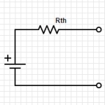
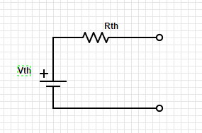
Any two terminal network of voltage sources and resistors can be replace by a single voltage source in combination with a single resistor. This is called the Thevenin’s equivalent circuit:
The first step is to identify the two terminals of the network.
Then to figure out Rth, replace any voltage sources with short circuits and any current sources with open circuits.
Calculate the voltage between the two terminals.
Then figure out Vth between the two terminals.
To figure this out using testing and measuring, it is only necessary to find the voltage at the two terminals with power on, and the resistance with power off.
This can greatly simplify circuit analysis of complex circuits.
Check out videos on YouTube with more detailed information:
Let’s take a look at the symbols for voltage sources and current sources. Also, let’s discuss the properties of the ideal voltage source and the ideal current source.
The ideal voltage source will maintain the same voltage between its terminals regardless of the load. This is easiest with an open circuit but becomes impossible with a short circuit.
The ideal current source will maintain the same current regardless of the resistance of the load. This is easy with an open circuit but becomes more and more difficult as the resistance increases.
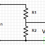
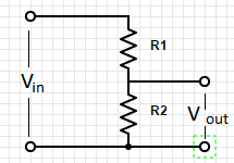
Voltage Dividers take an input voltage and gives you a smaller, fractional output voltage. This can be useful for volume control or when interfacing between logic circuits that run at 5V with new/lower power devices that run at 3.3V.
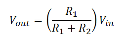
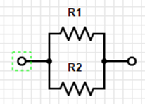
A voltage divider is a simple circuit made up of only two resistors (R1 & R2 in the diagram below).
Resistance (represented in formulas as “R”) measured in Ohms which is represented using the symbol:
Resistance is the relationship between Current (I) and Voltage (R).
This relationship is defined by Ohm’s law: R = V/I.
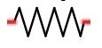
Circuit diagrams represent resistors as
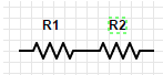
Resistors in Series: (Always bigger)
R= R1 + R2
Resistors in Parallel: (Always smaller)
R = (R1*R2)/(R1+R2)
Shortcut #1:
A large resistor in series with a small resistor has the resistance of the larger one, roughly.
A large resistor in parallel with a small resistor has the resistance of the smaller one, roughly.
Try to develop an intuitive sense of the voltage and current in the parts of the circuit. Do not try to calculate to be extremely precise because the precision of the components will make this pointless. Also, good circuit design should be tolerant of variations.
Power:
P=IV
Using Ohm’s law you get:
P=(I^2)R
P=(V^2)/R
Things good to learn
The inverse of resistance is conductance (represented by “G” in formulas) G=1/R
Restatement of Ohm’s law: I=GV
Conductance is measured in siemens
siemens is also known as mho (ohm spelled backwards)
Voltage & Current describe two aspects of electronic circuits that are fundamental to understand and on which everything else will build on.
What you MUST learn
Voltage refers to a force that when applied across a circuit causes current to flow. Voltage is measured in volts (using the symbol V) also called a “potential difference”. It is measured across two points in a circuit. A joule of work is needed to move a coulomb of charge through a potential difference of one volt. A coulomb is the charge of about 6×10^18 electrons.
Current (symbol: I) is the measure of electronics through a point in a circuit. It is measured in amperes (amps) (symbol: A). 1 ampere (amp) is 1 coulomb of charge passing through a point per second.
Conservation of Charge: Kirchhoff’s current law
The sum of currents into a point or node is equal to the sum of the currents out of a point or node. This is referred to as Kirchhoff’s current law.
Kirchhoff’s voltage law
The sum of voltage drops through one branch of a circuit will equal the sum of voltage drops across the other branches of the circuit.
P=VI
Power (work per unit time), measured in watts. (1 W = 1 J/s)
Voltage is usually written with the symbol V but sometimes E is used. Voltage is also called a “potential difference” or electromotive force (EMF).
Prefixes:
Multiple
Prefix
Symbol
10^12
tera
T
10^9
giga
G
10^6
mega
M
10^3
kilo
k
10^(-3)
milli
m
10^(-6)
micro
µ
10^(-9)
nano
n
10^(-12)
pico
p
10^(-15)
femto
f
When abbreviating a unit with a prefix, the unit follows the multiplier with no space and the unit is capitalized. However, no capitalization for both prefix and unit when spelled out. 1mW = 1 milliwatt
1 MV = 1 megavolt
Related information and insights from my other books
nucleus is made up of protons (that have a positive charge) and neutrons that have a negative charge. The proton and neutron are relatively the same mass. But the electron is considerably smaller (1836 times smaller) than the proton but has a negative charge that is equal to the positive charge of the proton.


 Resistors in Parallel: (Always smaller)